U5: pid monitors, For a complete list of u5 – Yaskawa Z1000U User Manual
Page 315
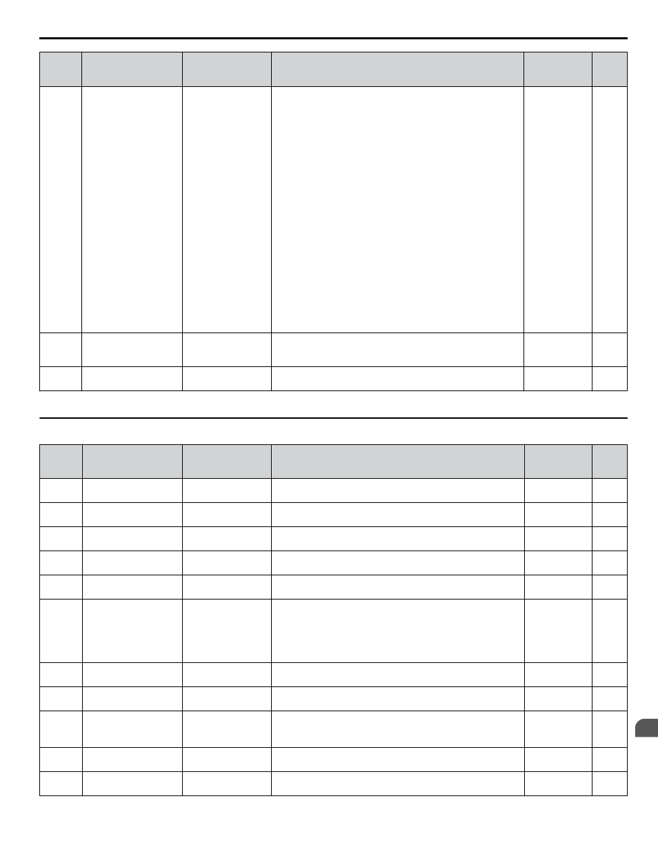
No.
(Addr.
Hex)
Name
LCD Display
Description
Analog
Output Level
Unit
U4-21
(07DD)
Run Command Source
Selection
Run Cmd Source
Displays the source for the Run command as XY-nn.
X: Indicates which Run source is used:
0 = OFF
1 = AUTO
2 = HAND
Y: Input power supply data
0 = HOA keypad
1 = External terminals
3 = Serial communications (APOGEE FLN, BACnet,
MEMOBUS/Modbus, or Metasys N2)
4 = Communication option card
nn: Run command limit status data
00: No limit status.
01: Run command was left on when stopped in the PRG mode
02: Run command was left on when switching from LOCAL to
REMOTE operation
03: Waiting for soft charge bypass contactor after power up (Uv
or Uv1 flashes after 10 s)
04: Waiting for “Run command prohibited” time period to end
05: Fast Stop (digital input, HOA keypad)
06: b1-17 (Run command given at power-up)
07: During baseblock while coast to stop with timer
08: Frequency reference is below minimal reference during
baseblock
09: Waiting for Enter command
No signal output
available
–
U4-22
(07DE)
MEMOBUS/Modbus
Communications
Reference
MEMOBUS Ref Reg
Displays the drive control data set by MEMOBUS/Modbus
communications register no. 0001H as a four-digit hexadecimal
number.
No signal output
available
–
U4-23
(07DF)
Communication Option
Card Reference
Option Ref Reg
Displays drive control data set by an option card as a four-digit
hexadecimal number.
No signal output
available
–
<1> When reading the value of this monitor via MEMOBUS/Modbus, a value of 8192 is equal to 100% of the drive rated output current.
u
U5: PID Monitors
No.
(Addr.
Hex)
Name
LCD Display
Description
Analog
Output Level
Unit
U5-01
(0057)
PID Feedback
PID Feedback 1
Displays the PID feedback value.
10 V: 100%
0.01%
U5-02
(0063)
PID Input
PID Input
Displays the amount of PID input (deviation between PID
setpoint and feedback).
10 V: 100%
0.01%
U5-03
(0064)
PID Output
PID Output
Displays PID control output.
10 V: 100%
0.01%
U5-04
(0065)
PID Setpoint
PID Setpoint
Displays the PID setpoint.
10 V: 100%
0.01%
U5-05
(07D2)
PID Differential
Feedback
PID Feedback 2
Displays the second PID feedback value if differential feedback
is used (H3-oo = 16).
10 V: 100%
0.01%
U5-06
(07D3) PID Adjusted Feedback PID Diff Fdbk
Displays the difference of both feedback values if Differential
Feedback is used (U5-01 - U5-05).
If PID Square Root Feedback or Differential Feedback are
enabled, U5-01
≠ U5-06.
If PID Square Root Feedback or Differential Feedback are NOT
enabled, U5-01= U5-06.
10 V: 100%
0.01%
U5-07
(72)
AUTO Mode Frequency
Reference Value
AUTO mode Fref
Displays the Frequency reference value at AUTO Mode.
No signal output
available
0.01 Hz
U5-08
(0073)
HAND Mode Frequency
Reference Value
HAND mode Fref
Displays the Frequency reference value at HAND Mode.
No signal output
available
0.01 Hz
U5-14
(086B)
PID Output Upper 4
Digits
PID Output U4
Displays Custom PID output. U5-14 shows the upper 4 digits.
10V: (b5-43 x
10000) + b5-44
<1>
1
U5-15
(086C)
PID Output Lower 4
Digits
PID Output L4
Displays Custom PID output. U5-15 shows the lower 4 digits.
No signal output
available
0.01
U5-17
(302A) PI2 Setpoint
PI2 Set-point
Displays the secondary PI setpoint.
10 V: Max
frequency
0.01%
B.14 U: Monitors
YASKAWA ELECTRIC TOEP C710636 10B Z1000U HVAC MATRIX Drive User Manual
315
B
Parameter List