Connecting a surge absorber, Reducing noise, Attachment for external heatsink mounting – Yaskawa Z1000U User Manual
Page 239: Failure to comply may cause resistor
u
Installing a Magnetic Contactor at the Power Supply Side
Install a magnetic contactor (MC) to the drive input for the purposes explained below.
n
Disconnecting the Power Supply
Shut off the drive with an MC when a fault occurs in external equipment.
NOTICE: Do not connect electromagnetic switches or MCs to the output motor circuits without proper sequencing. Improper sequencing of
output motor circuits could result in damage to the drive.
NOTICE: Install an MC on the input side of the drive when the drive should not automatically restart after power loss. To get the full
performance life out of the capacitor for the control power supply and circuit relays, refrain from switching the drive power supply off and on
more than once every 30 minutes. Frequent use can damage the drive. Use the drive to stop and start the motor.
NOTICE: Use a magnetic contactor (MC) to ensure that power to the drive can be completely shut off when necessary. The MC should be
wired so that it opens when a fault output terminal is triggered.
Note:
1. Install an MC to the drive input side to prevent the drive from restarting automatically when power is restored after momentary power
loss.
2. Set up a delay that prevents the MC from opening prematurely to continue operating the drive through a momentary power loss.
u
Connecting a Surge Absorber
A surge absorber suppresses surge voltage generated from switching an inductive load near the drive. Inductive loads include
magnetic contactors, relays, valves, solenoids, and brakes. Always use a surge absorber or diode when operating with an
inductive load.
WARNING! Fire Hazard. Due to surge absorber short circuit on drive output terminals U/T1, V/T2, and W/T3, do not connect surge absorbers
to the drive output power terminals. Failure to comply may result in serious injury or death by fire or flying debris.
u
Reducing Noise
n
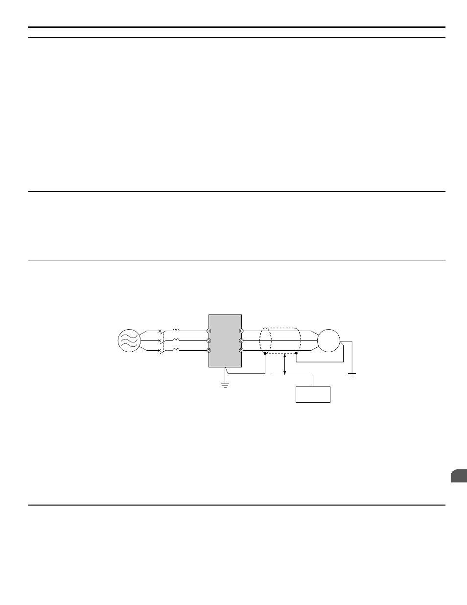
Preventing Induced Noise
Use shielded cables or zero phase reactors and lay the cables at least 30 cm away from the signal line to prevent induced noise.
B
A
C
F
G
E
R/L1
MCCB
S/L2
T/L3
U/T1
V/T2
W/T3
D
M
A – Power supply
B – Drive
C – Shielded motor cable
D – Motor
E – Separate at least 30 cm
F – Controller
G – Signal line
Figure 6.10 Preventing Induced Noise
n
Reducing Noise Using Internal EMC Filter Models
Models ZUoEoooo and ZUoWoooo contain a built-in EMC filter. These drives comply with EMC guidelines IEC/
EN 61800-3 2nd Environment Category C2. Use switches on the drive to enable the EMC filters.
for details.
u
Attachment for External Heatsink Mounting
An external attachment can be used to project the heatsink outside of an enclosure to ensure that there is sufficient air circulation
around the heatsink.
6.5 Installing Peripheral Devices
YASKAWA ELECTRIC TOEP C710636 10B Z1000U HVAC MATRIX Drive User Manual
239
6
Peripheral Devices & Options