Yaskawa Z1000U User Manual
Page 364
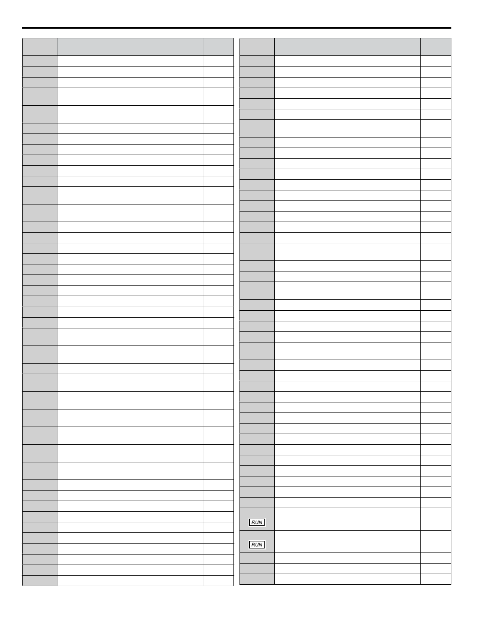
No.
Name
User
Setting
H5-15
BACnet Device Object ID
L1-01
Motor Overload Protection Selection
L1-02
Motor Overload Protection Time
L1-03
Motor Overheat Alarm Operation Selection (PTC
input)
L1-04
Motor Overheat Fault Operation Selection (PTC
input)
L1-05
Motor Temperature Input Filter Time (PTC input)
L1-08
oL1 Current Level
L1-13
Continuous Electrothermal Operation Selection
L2-01
Momentary Power Loss Operation Selection
L2-02
Momentary Power Loss Ride-Thru Time
L2-03
Momentary Power Loss Minimum Baseblock Time
L2-04
Momentary Power Loss Voltage Recovery Ramp
Time
L2-07
Momentary Power Loss Voltage Recovery
Acceleration Time
L2-13
Input Power Frequency Fault Detection Gain
L2-21
Low Input Voltage Detection Level
L2-27
Power Supply Frequency Fault Detection Width
L3-01
Stall Prevention Selection during Acceleration
L3-02
Stall Prevention Level during Acceleration
L3-03
Stall Prevention Limit during Acceleration
L3-04
Stall Prevention Selection during Deceleration
L3-05
Stall Prevention Selection during Run
L3-06
Stall Prevention Level during Run
L3-14
Stall Prevention Level during Deceleration
L3-22
Deceleration Time at Stall Prevention during
Acceleration
L3-23
Automatic Reduction Selection for Stall Prevention
during Run
L3-27
Stall Prevention Detection Time
L3-36
Vibration Suppression Gain during Acceleration
(with Current Limit)
L3-39
Current-Limited Integral Time Constant during
Acceleration
L3-40
Current-Limited Maximum S-curve Selection
during Acceleration
L3-41
Vibration Suppression Gain during Deceleration
(with Current Limit)
L3-44
Current-Limited Integral Time Constant during
Deceleration
L3-45
Current-Limited Maximum S-curve Selection
during Deceleration
L4-01
Speed Agreement Detection Level
L4-02
Speed Agreement Detection Width
L4-03
Speed Agreement Detection Level (+/-)
L4-04
Speed Agreement Detection Width (+/-)
L4-05
Frequency Reference Loss Detection Selection
L4-06
Frequency Reference at Reference Loss
L4-07
Speed Agreement Detection Selection
L5-01
Number of Auto Restart Attempts
L5-02
Auto Restart Fault Output Operation Selection
L5-03
Time to Continue Making Fault Restarts
No.
Name
User
Setting
L5-04
Fault Reset Interval Time
L5-05
Fault Reset Operation Selection
L6-01
Torque Detection Selection 1
L6-02
Torque Detection Level 1
L6-03
Torque Detection Time 1
L6-13
Motor Underload Protection Selection
L6-14
Motor Underload Protection Level at Minimum
Frequency
L8-02
Overheat Alarm Level
L8-03
Overheat Pre-Alarm Operation Selection
L8-06
Input Phase Loss Detection Level
L8-07
Output Phase Loss Protection
L8-09
Output Ground Fault Detection Selection
L8-10
Heatsink Cooling Fan Operation Selection
L8-11
Heatsink Cooling Fan Off Delay Time
L8-12
Ambient Temperature Setting
L8-15
oL2 Characteristics Selection at Low Speeds
L8-18
Software Current Limit Selection
L8-19
Frequency Reduction Rate during Overheat
Pre-Alarm
L8-27
Overcurrent Detection Gain
L8-29
Current Unbalance Detection (LF2)
L8-32
Main Contactor and Cooling Fan Power Supply
Failure Selection
L8-35
Installation Method Selection
L8-38
Carrier Frequency Reduction Selection
L8-40
Carrier Frequency Reduction Off-Delay Time
L8-41
High Current Alarm Selection
L8-97
Carrier Frequency Reduction Selection during oH
Pre-Alarm
L9-03
Carrier Frequency Reduction Level Selection
n1-01
Hunting Prevention Selection
n1-02
Hunting Prevention Gain Setting
n1-03
Hunting Prevention Time Constant
n1-05
Hunting Prevention Gain while in Reverse
n3-13
Overexcitation Deceleration Gain
n8-45
Speed Feedback Detection Control Gain
n8-47
Pull-In Current Compensation Time Constant
n8-48
Pull-In Current
n8-49
d-Axis Current for High Efficiency Control
n8-51
Acceleration/Deceleration Pull-In Current
n8-54
Voltage Error Compensation Time Constant
n8-55
Load Inertia
n8-62
Output Voltage Limit
o1-01
Drive Mode Unit Monitor Selection
o1-02
User Monitor Selection After Power Up
o1-03
Digital Operator Display Selection
o1-05
LCD Contrast Control
o1-06
User Monitor Selection Mode
E.3 User Setting Table
364
YASKAWA ELECTRIC TOEP C710636 10B Z1000U HVAC MATRIX Drive User Manual