Terminal configuration, Wire size and torque specifications, Ferrule-type wire terminals – Yaskawa Z1000U User Manual
Page 84: 9 control circuit wiring
u
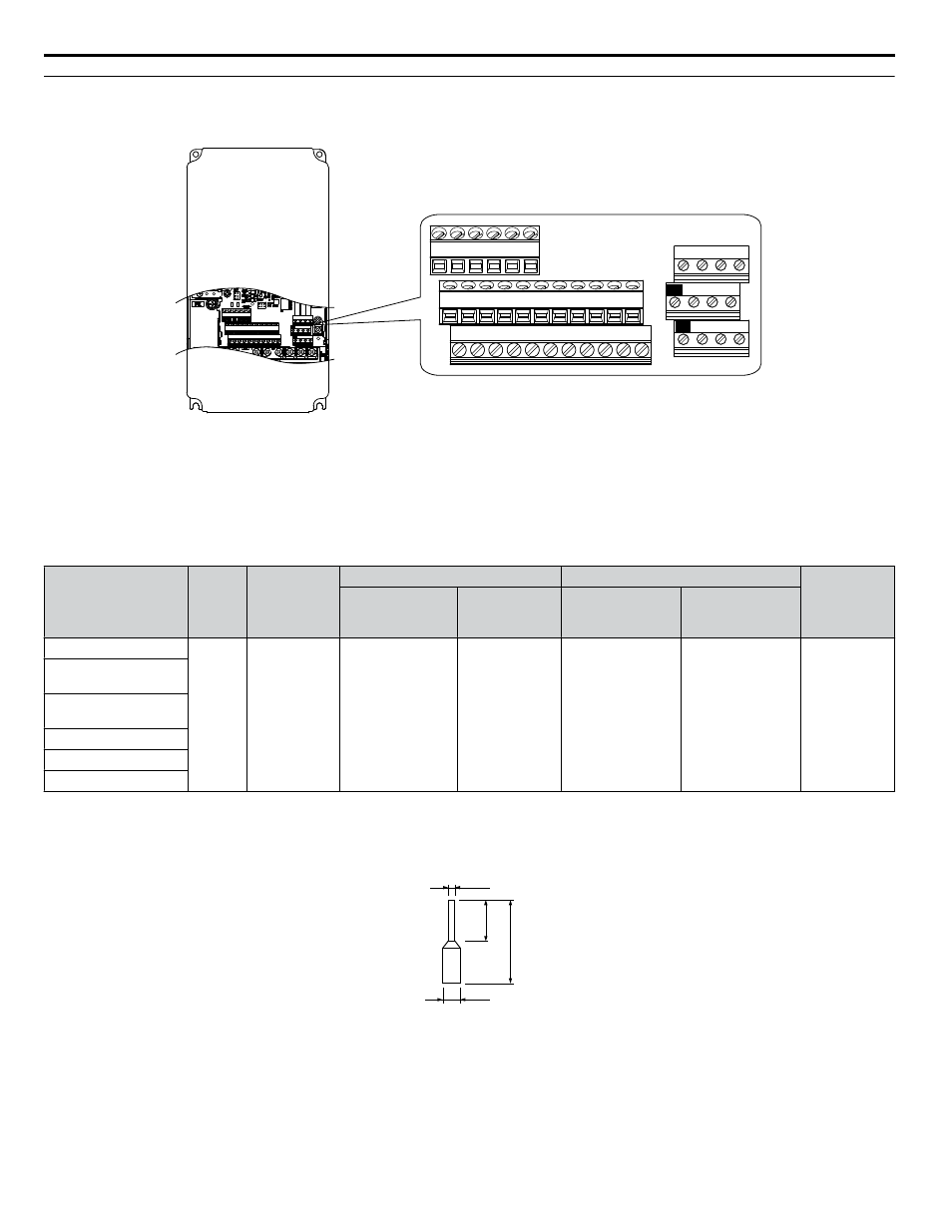
Terminal Configuration
The control circuit terminals are arranged as shown in
E(G) IG R+ R- S+ S-
S1 S2 S3 S4 S5 S6 S7 S8 SN SC SP
V+ AC A1 A2 A3 FM AM AC
24V
RP AC
M1 M2 M3 M4
MD ME MF
MA MB MC
E(G) IG R+ R- S+ S-
S1 S2 S3 S4 S5 S6 S7 S8 SN SC SP
V+ AC A1 A2 A3 FM AM AC
24V
RP AC
M1 M2 M3 M4
MD ME MF
MA MB MC
Figure 3.34 Control Circuit Terminal Arrangement
n
Wire Size and Torque Specifications
Select appropriate wire type and gauges from
. For simpler and more reliable wiring, use crimp ferrules on the wire
ends.
Table 3.10 Wire Gauges
Terminal
Screw
Size
Tightening
Torque
N
•m
(lb. in)
Bare Wire Terminal
Ferrule-Type Terminal
Wire Type
Applicable
wire size
mm
2
(AWG)
Recomm.
wire size
mm
2
(AWG)
Applicable
wire size
mm
2
(AWG)
Recomm.
wire size
mm
2
(AWG)
S1-S8, SC, SN, SP
M3
0.5 to 0.6
(4.4 to 5.3)
Stranded wire:
0.2 to 1.0
(24 to 16)
Solid wire:
0.2 to 1.5
(24 to 16)
0.75 (18)
0.25 to 0.5
(24 to 20)
0.5 (20)
Shielded wire,
etc.
RP, V+, A1, A2, A3,
AC, 24 V
MA, MB, MC, MD, ME,
MF
M1-M4
FM, AM, AC
R+, R-, S+, S-, IG
n
Ferrule-Type Wire Terminals
Yaskawa recommends using CRIMPFOX 6, a crimping tool manufactured by PHOENIX CONTACT, to prepare wire ends
with insulated sleeves before connecting to the drive. See
d1
d2
8 mm
L
Figure 3.35 Ferrule Dimensions
3.9 Control Circuit Wiring
84
YASKAWA ELECTRIC TOEP C710636 10B Z1000U HVAC MATRIX Drive User Manual