F5: digital output card settings (do-a3), F6, f7: communication option card settings – Yaskawa Z1000U User Manual
Page 272
No.
(Addr.
Hex)
Name
LCD Display
Description
Values
Page
F4-05
(0395)
Terminal V1 Monitor
Bias
AO Ch1 Bias
Sets the amount of bias added to the voltage output via terminal
V1.
Default: 0.0%
Min.: -999.9
Max.: 999.9
–
F4-06
(0396)
Terminal V2 Monitor
Bias
AO Ch2 Bias
Sets the amount of bias added to the voltage output via terminal
V2.
Default: 0.0%
Min.: -999.9
Max.: 999.9
–
F4-07
(0397)
Terminal V1 Signal
Level
AO Opt Level Ch1
0: 0-10 VDC
1: -10 +10 VDC
0: 0 to 10 V
1: -10 to 10 V
Default: 0
Range: 0, 1
–
F4-08
(0398)
Terminal V2 Signal
Level
AO Opt Level Ch2
0: 0-10 VDC
1: -10 +10 VDC
0: 0 to 10 V
1: -10 to 10 V
Default: 0
Range: 0, 1
–
u
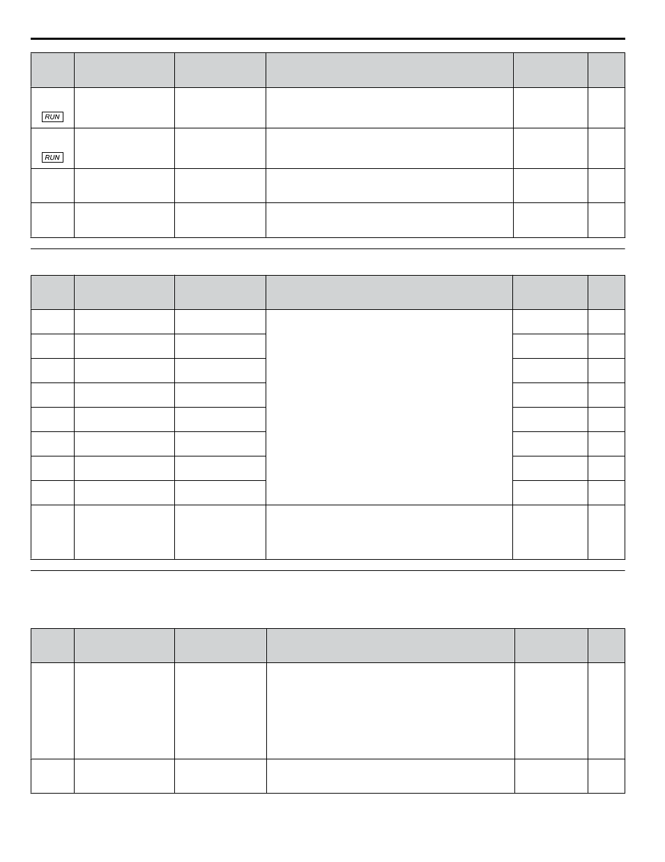
F5: Digital Output Card Settings (DO-A3)
No.
(Addr.
Hex)
Name
LCD Display
Description
Values
Page
F5-01
(0399)
Terminal P1-PC Output
Selection
DO Ch1 Select
Sets the function for contact output terminals M1-M2, M3-M4,
and photocoupler output terminals P1 through P6.
Default: 0
Range: 0 to 1B6
–
F5-02
(039A)
Terminal P2-PC Output
Selection
DO Ch2 Select
Default: 1
Range: 0 to 1B6
–
F5-03
(039B)
Terminal P3-PC Output
Selection
DO Ch3 Select
Default: 2
Range: 0 to 1B6
–
F5-04
(039C)
Terminal P4-PC Output
Selection
DO Ch4 Select
Default: 4
Range: 0 to 1B6
–
F5-05
(039D)
Terminal P5-PC Output
Selection
DO Ch5 Select
Default: 6
Range: 0 to 1B6
–
F5-06
(039E)
Terminal P6-PC Output
Selection
DO Ch6 Select
Default: 37
Range: 0 to 1B6
–
F5-07
(039F)
Terminal M1-M2
Output Selection
DO Ch7 Select
Default: F
Range: 0 to 1B6
–
F5-08
(03A0)
Terminal M3-M4
Output Selection
DO Ch8 Select
Default: F
Range: 0 to 1B6
–
F5-09
(03A1)
DO-A3 Output Mode
Selection
DO Function Sel
0: Output terminals are each assigned separate output
functions.
1: Binary code output.
2: Use output terminal functions selected by parameters F5-01
through F5-08.
Default: 0
Range: 0 to 2
–
u
F6, F7: Communication Option Card Settings
Parameters F6-01 through F6-03 and F6-06 through F6-08 are used for EtherNet/IP, Modbus TCP/IP, and LONWORKS
options. F7 parameters are used for the EtherNet/IP and Modbus TCP/IP options.
No.
(Addr.
Hex)
Name
LCD Display
Description
Values
Page
F6-01
(03A2)
Communications Error
Operation Selection
Comm Bus Flt Sel
0: Ramp to Stop
1: Coast to Stop
2: Fast-Stop
3: Alarm Only
4: Alarm (d1-04)
5: Alm – Ramp Stop
0: Ramp to stop. Decelerate to stop using the deceleration time
in C1-02.
1: Coast to stop.
2: Fast Stop. Decelerate to stop using the deceleration time in
C1-09.
3: Alarm only.
<1>
4: Alarm only. Continue operation using the frequency
reference set in d1-04.
<1>
5: Alarm. Ramp to stop.
Default: 1
Range: 0 to 5
–
F6-02
(03A3)
External Fault from
Comm. Option
Detection Selection
EF0 Detection
0: Always Detected
1: Only During Run
0: Always detected.
1: Detection during run only.
Default: 0
Range: 0, 1
–
B.7 F: Option Settings
272
YASKAWA ELECTRIC TOEP C710636 10B Z1000U HVAC MATRIX Drive User Manual