Main circuit connection diagram, 3 main circuit connection diagram – Yaskawa Z1000U User Manual
Page 59
Advertising
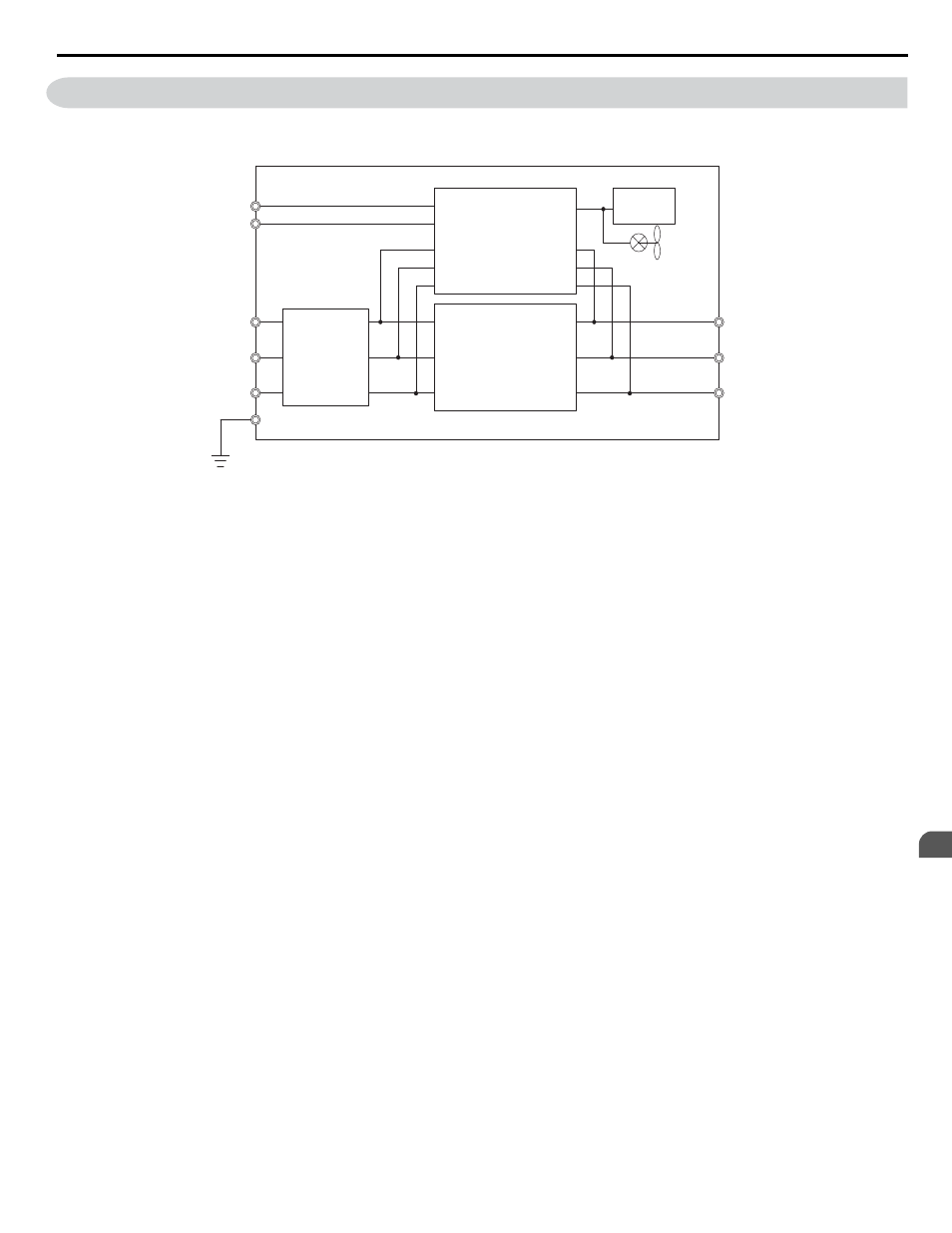
3.3 Main Circuit Connection Diagram
Refer to
when wiring the main circuit of the drive. Connections may vary based on drive capacity. The DC power
supply for the main circuit also provides power to the control circuit.
Input filter
R/L1
S/L2
T/L3
U/T1
V/T2
W/T3
Control
board
Bidirectional IGBT
Control power supply
p1
n1
Figure 3.2 Connecting Main Circuit Terminals
3.3 Main Circuit Connection Diagram
YASKAWA ELECTRIC TOEP C710636 10B Z1000U HVAC MATRIX Drive User Manual
59
3
Electrical Installation
Advertising
This manual is related to the following products: