Figure, Figure 3.37, 9 control circuit wiring – Yaskawa Z1000U User Manual
Page 86
Advertising
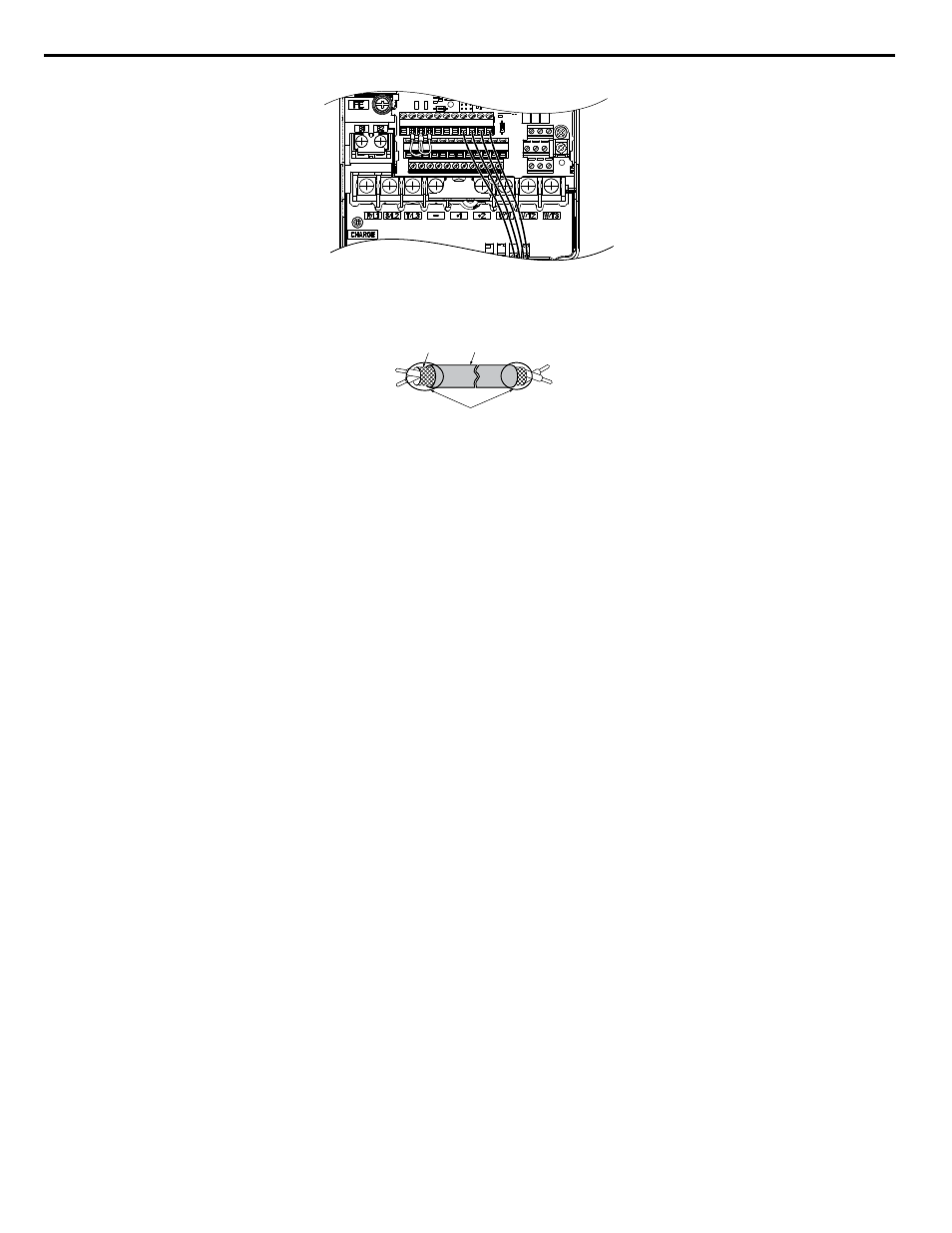
Figure 3.37 Terminal Board Location Inside the Drive
A
E
B
C
D
A – Drive side
B – Insulation
C – Control device side
D – Shield sheath (insulate with tape)
E – Shield
Figure 3.38 Preparing the Ends of Shielded Cables
NOTICE: The analog signal wiring between the drive and the operator station or peripheral equipment should not exceed 50 meters when
using an analog signal from a remote source to supply the frequency reference. Failure to comply could result in poor system performance.
3.9 Control Circuit Wiring
86
YASKAWA ELECTRIC TOEP C710636 10B Z1000U HVAC MATRIX Drive User Manual
Advertising
This manual is related to the following products: