Three-phase, 200 v, 2) servopack main circuit wires, Single-phase, 100 v – Yaskawa Sigma-5 User Manual: Setup for Linear Motors User Manual
Page 107
3.3 Main Circuit Wiring
3-23
3
Wiring and Connection
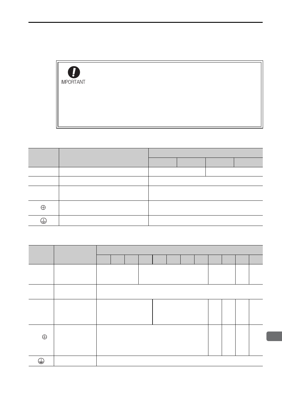
(2) SERVOPACK Main Circuit Wires
The wires used in the SERVOPACK main circuit are described below.
Single-phase, 100 V
Three-phase, 200 V
• Wire sizes are selected for three cables per bundle at 40
°C sur-
rounding air temperature with the rated current.
• Use a wire with a minimum withstand voltage of 600 V for the
main circuit.
• If cables are bundled in PVC or metal ducts, take into account the
reduction of the allowable current.
• Use a heat-resistant wire under high surrounding air or panel
temperatures, where polyvinyl chloride insulated wires will rapidly
deteriorate.
Terminal
Symbols
Terminal Names
SERVOPACK Model SGDV-F
R70
R90
2R1
2R8
L1, L2
Main circuit power input terminals
HIV1.25
HIV2.0
L1C, L2C
Control power input terminals
HIV1.25
U, V, W
Linear servomotor connection
terminals
HIV1.25
B1/
, B2
External regenerative resistor
connection terminals
HIV1.25
Ground terminal
HIV2.0 or higher
Terminal
Symbols Terminal Names
SERVOPACK Model SGDV-A
R70 R90 1R6 2R8 3R8 5R5 7R6 120 180 200 330 550
L1, L2,
L3
Main circuit
power input
terminals
HIV1.25
HIV2.0
HIV3.5
HIV
5.5
HIV
14.0
L1C,
L2C
Control power
input terminals
HIV1.25
U, V, W
Linear
servomotor
connection
terminals
HIV1.25
HIV2.0
HIV
3.5
HIV
5.5
HIV
8.0
HIV
14.0
B1/
,
B2
External
regenerative
resistor
connection
terminals
HIV1.25
HIV
2.0
HIV
3.5
HIV
5.5
HIV
8.0
Ground terminal
HIV2.0 or higher