3 setting the servopack parameters, 1 setting and checking the linear scale pitch – Yaskawa Sigma-5 User Manual: Setup for Linear Motors User Manual
Page 140
5 Trial Operation (Checking Linear Servomotor Operation)
5.3.1 Setting and Checking the Linear Scale Pitch
5-4
5.3
Setting the SERVOPACK Parameters
Set the following SERVOPACK parameters.
• Linear scale pitch (Pn282)
• Hall sensor selection (Pn080.0)
• Motor phase selection (Pn080.1)
• Overtravel signal mapping (Pn50A.3, Pn50B.0)
• Force limit (Pn483, Pn484)
5.3.1 Setting and Checking the Linear Scale Pitch
(1) When Using a Serial Converter Unit
Turn ON the control power supply.
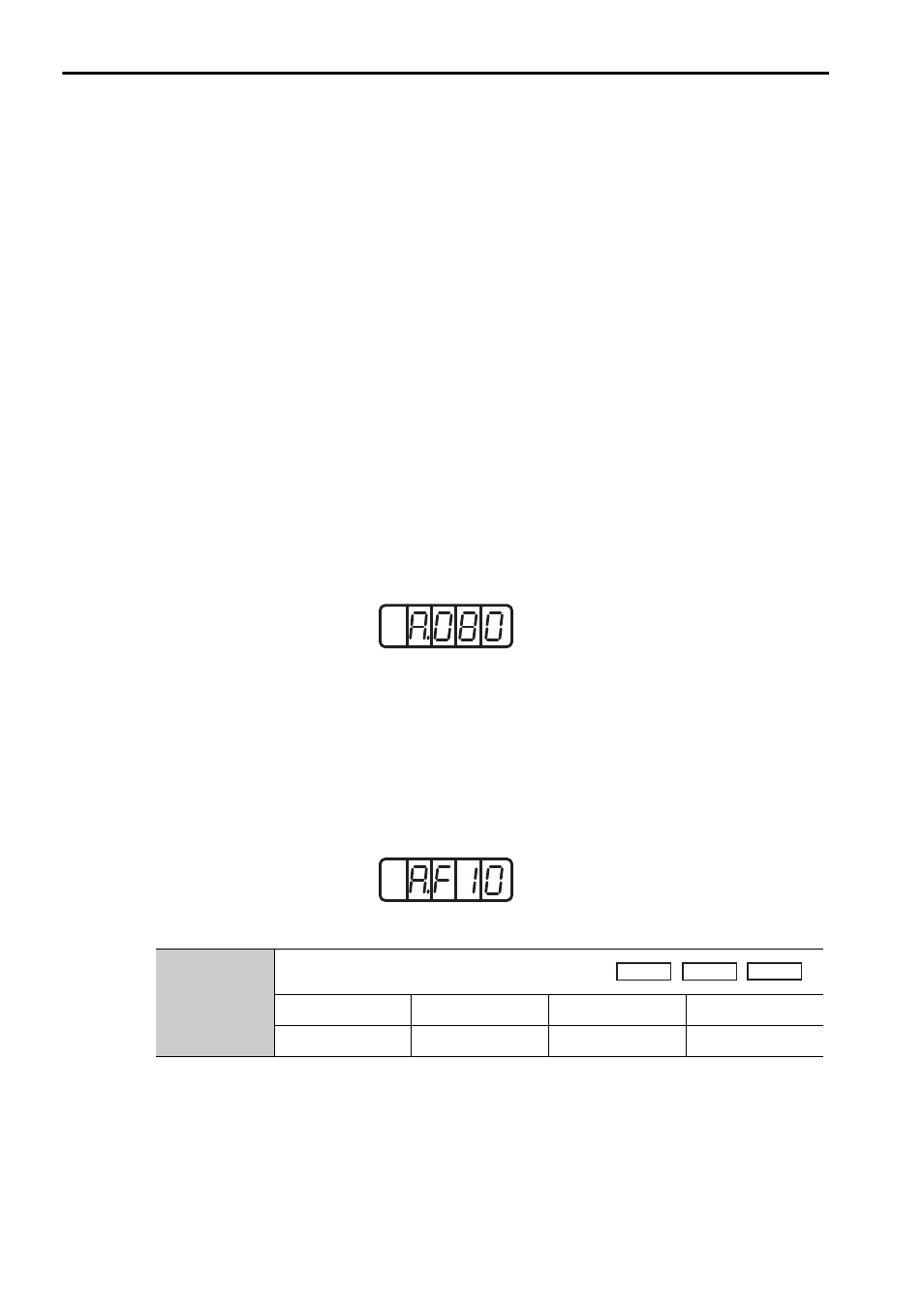
When the power is supplied normally, the panel operator on the front panel of the
SERVOPACK will show the following display. A linear scale pitch setting error
(A.080) will be displayed, but does not indicate an error. Set the linear scale pitch
(Pn282) according to the scale being used. After setting validation of the control
power, the A.080 alarm will be cleared, and the settings will be enabled.
If an alarm other than A.080 is displayed, as shown in the following diagram, the wir-
ing for the power supply circuit, the linear servomotor main circuit cable or the cable
for connecting the serial converter unit is the probable cause. Shut down the power
supply, specify the location causing the alarm, and take corrective measures so that
the display returns to the above normal status. For details on alarms, refer to the cor-
responding SERVOPACK or command option module user’s manual (see
Manu-
als Related to the
Σ
-V Series in About this Manual.)
If the linear scale pitch (Pn282) is not set correctly, the linear servomotor cannot be
controlled. Make sure that the correct value is set before operating the linear servo-
motor.
Pn282
Linear Scale Pitch
Setting Range
Setting Unit
Factory Setting
When Enabled
0 to 6553600
0.01
μm
0
After restart
Normal status
Example of alarm display
Speed
Position
Force