About this manual – Yaskawa Sigma-5 User Manual: Setup for Linear Motors User Manual
Page 3
iii
About this Manual
This manual describes procedures required for installation, wiring, and connecting
Σ-V Series servo drives, including a JOG operation for linear servomotors not con-
nected to machinery.
Be sure to refer to this manual and perform setup operations correctly.
Keep this manual in a location where it can be accessed for reference whenever
required.
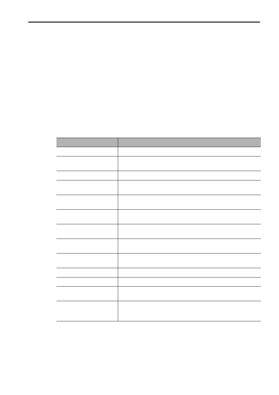
Description of Technical Terms
The following table shows the meanings of terms used in this manual.
Term
Meaning
Cursor
Input position indicated by Digital Operator
Linear Servomotor
Σ-V Series SGLGW, SGLFW, SGLTW, or SGLC linear servomo-
tor, or SGT linear slider
SERVOPACK
Σ-V Series SGDV SERVOPACK
Servo Drive
A set including a linear servomotor and SERVOPACK (i.e., a
servo amplifier)
Servo System
A servo control system that includes the combination of a servo
drive with a host controller and peripheral devices
Analog Pulse Model
Analog voltage and pulse-train reference used for SERVOPACK
interface.
M-II Model
MECHATROLINK-II communications reference used for
SERVOPACK interface.
M-III Model
MECHATROLINK-III communications reference used for
SERVOPACK interface.
Command Option
Attachable Type
SERVOPACK for which a command option module can be
installed.
Servo ON
Power to motor ON
Servo OFF
Power to motor OFF
Base Block (BB)
Power supply to motor is turned OFF by shutting off the base cur-
rent to the power transistor in the current amplifier.
Linear Scale Connection
Cables
A set of cables including a cable for connecting serial converter
unit, a cable for connecting linear scale, and a cable for connect-
ing hall sensor