Yaskawa Sigma-5 User Manual: Setup for Linear Motors User Manual
Page 123
3.4 Connecting Regenerative Resistors
3-39
3
Wiring and Connection
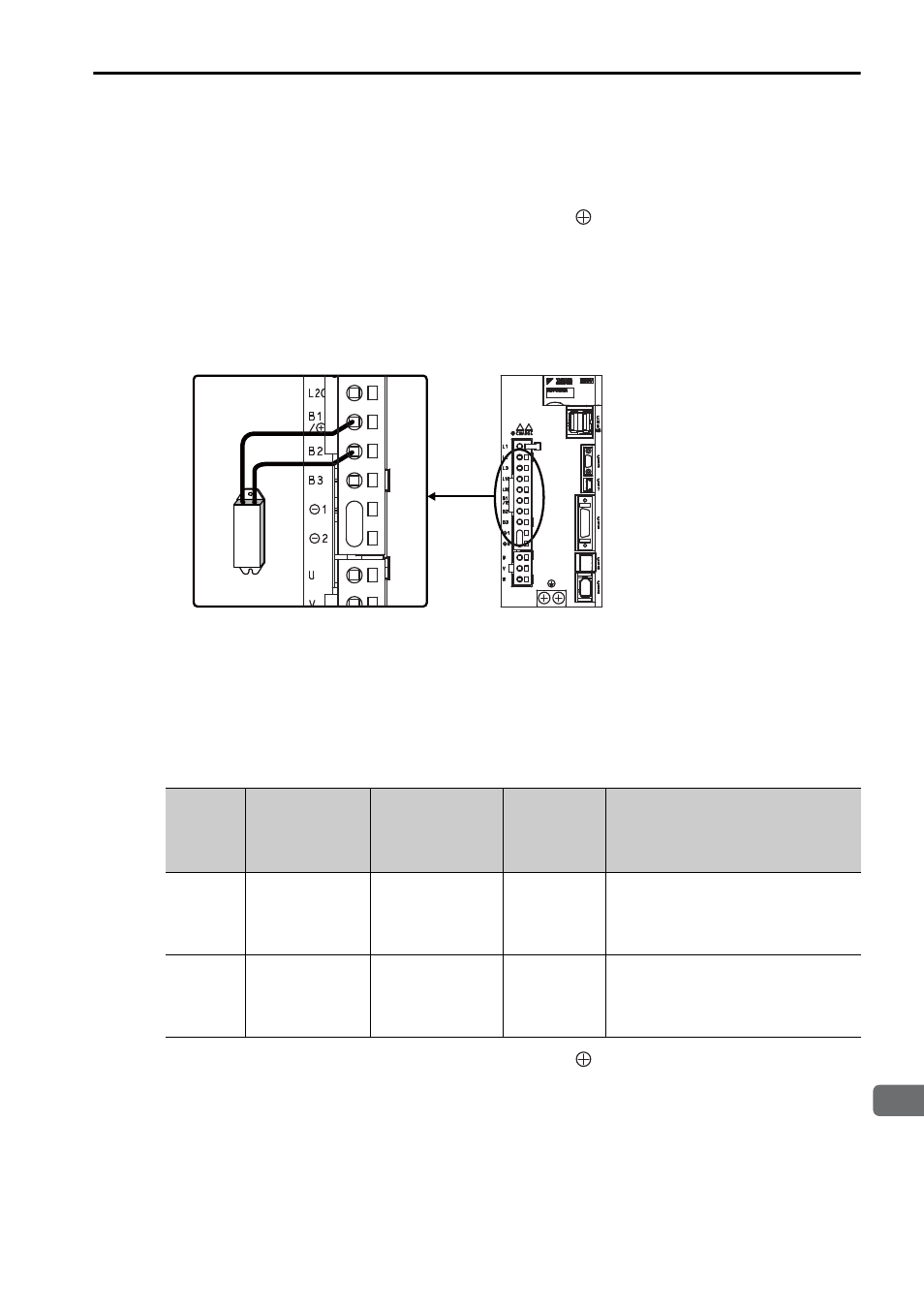
(2) SERVOPACKs: Model SGDV-3R8A, 5R5A, 7R6A, 120A, 180A,
200A, 330A, 1R9D, 3R5D, 5R4D, 8R4D, 120D, 170D
Disconnect the wiring between the SERVOPACK’s B2 and B3 terminals and connect
an external regenerative resistor between the B1/ and B2 terminals. After connect-
ing a resistor, set the regenerative resistor capacity. Refer to 3.4.2 Setting the Regen-
erative Resistor Capacity for information on how to set the regenerative resistor
capacity.
Note: Be sure to take out the lead wire between the B2 and B3 terminals.
(3) SERVOPACKs: Model SGDV-550A, 260D
No built-in regenerative resistor is provided, so the external regenerative resistor is
required. The following regenerative resistor units are available as option:
Note: The regenerative resistor unit is constructed from a number of resistors.
Connect a regenerative resistor unit between B1/ and B2 terminals.
Enlarged View
Main
Circuit
Power
Supply
SERVOPACK
Model SGDV-
Applicable
Regenerative
Resistor Unit
Resistance
(
Ω)
Specifications
Three-
phase
200 V
550A
JUSP-RA05-E
3.13
Eight 25
Ω (220 W) resistors are
connected in parallel.
Three-
phase
400 V
260D
JUSP-RA18-E
18
Two series of two 18
Ω (220 W)
resistors each are connected in
parallel.