Spi decoding (option), Spi decoding (option) -14 – RIGOL MSO/DS2000A Series User Manual
Page 192
RIGOL
8-14
MSO2000A/DS2000A User’s Guide
SPI Decoding (Option)
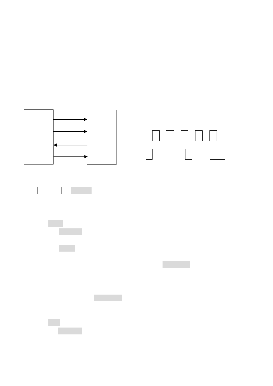
SPI bus is based on the master-slave configuration and usually consists of chip select
line (CS), clock line (SCLK) and data line (SDA). Wherein, the data line includes MISO
and MOSI.
SCLK: sample the SDA on the clock rising edge or falling edge.
SDA: denote the data channel.
Master
Slave
MOSI
SCLK
MISO
CS
SCLK
SDA
(MISO/MOSI)
Figure 8-11 SPI Serial Bus
Press Decode1 Decode to select “SPI” and open the SPI decoding function
menu.
1. SCLK Setting
Press SCLK to enter the clock line setting interface.
Press Channel to select any channel (CH1, CH2 or any channel of D0-D15)
as the clock channel.
Press Slope to set to sample the SDA on the rising or falling edge of the
SCLK.
If the clock channel is set to CH1 or CH2, press Threshold to set the
threshold of the clock channel. The range of the threshold is decided by the
vertical position and scale, and is from (-5 * vertical scale - vertical position)
to (5 * vertical scale - vertical position). If the clock channel is set to any
channel of D0-D15, Threshold will be hidden automatically.
2. SDA Setting
Press SDA to enter the SDA data line setting interface.
Press Channel to select any channel (CH1, CH2 or any channel of D0-D15)
as the data channel. If “OFF” is seelcted, this data line will not be set.