ProSoft Technology MVI56-PDPMV1 User Manual
Page 230
Reference
MVI56-PDPMV1 ♦ ControlLogix Platform
User Manual
PROFIBUS DPV1 Master
Page 230 of 255
ProSoft Technology, Inc.
March 22, 2011
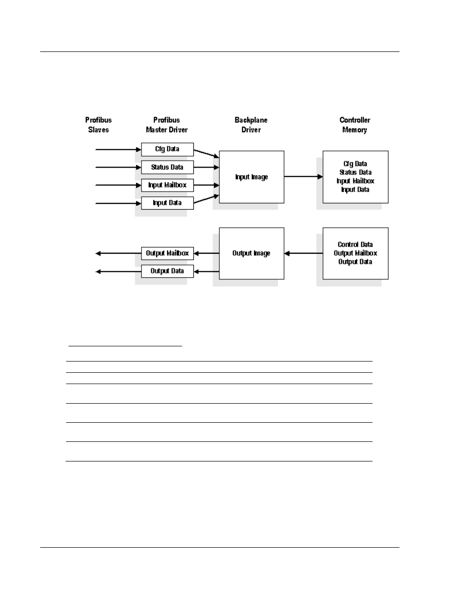
5.4.1 Legacy Mode Input and Output Data Blocks
The following illustration shows how the transfer of user data, mailbox block, and
status data is performed between the MVI56-PDPMV1 and the ControlLogix
processor.
The blocks that are transferred between the module and the processor can
perform different tasks, according to the Block ID numbers, as listed in the
following table.
Block ID Numbers for Transfer
Block #s
Type
Description
-1 or 0
Status
Block containing status data (refer to Status Objects)
1 to 4
Input Data
Input data from PROFIBUS network with each block containing up
to 200 words of data (refer to Input Data Block)
1 to 4
Output Data
Output data for PROFIBUS network with each block containing up
to 200 words of data (refer to Output Data Block)
100 to 109
Mailbox
These block numbers send or receive mailbox messages (refer to
PDPMV1_Mailbox data type)
200 to 209
Alarms
These block numbers send alarm messages from the PROFIBUS
network to the processor (refer to PDPMV1_Alarm).
The size of the input and output areas should be set to the smallest possible
values to maximize data throughput.
Handshaking is required between the in and out messages used by the module
and the controller.