ProSoft Technology MVI56-PDPMV1 User Manual
Page 236
Reference
MVI56-PDPMV1 ♦ ControlLogix Platform
User Manual
PROFIBUS DPV1 Master
Page 236 of 255
ProSoft Technology, Inc.
March 22, 2011
Word Offset
Start
End
Name
Description
204
205
PROFIBUS CRC32
value
Computed for PROFIBUS Config
206
207
Module CRC32 value
Computed for module data
When the module first starts up or recognizes an initialization
of the processor, it will compare the values of the two CRC’s in
the input and output images. If either one of the CRCs do not
match, the module will be placed in Stop mode. If each set
matches, the module will be placed in Operate mode.
208
247
Reserved
Reserved for future use
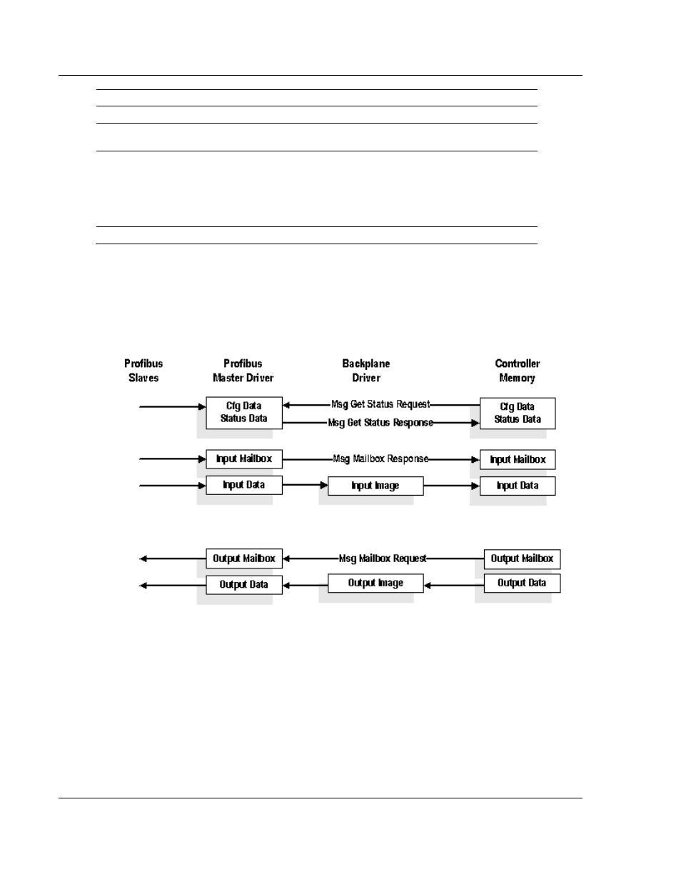
5.4.2 Flex Mode Input and Output Data Blocks
The following illustration shows how the transfer of data, mailbox block, and
status data is performed between the MVI56-PDPMV1 and the ControlLogix
processor.
The PROFIBUS I/O data is transferred through the backplane I/O images. The
status and mailbox data is transferred through MSG instructions.