NETGEAR M4350-24F4V 24-Port 10G SFP+ Managed AV Network Switch User Manual
Page 168
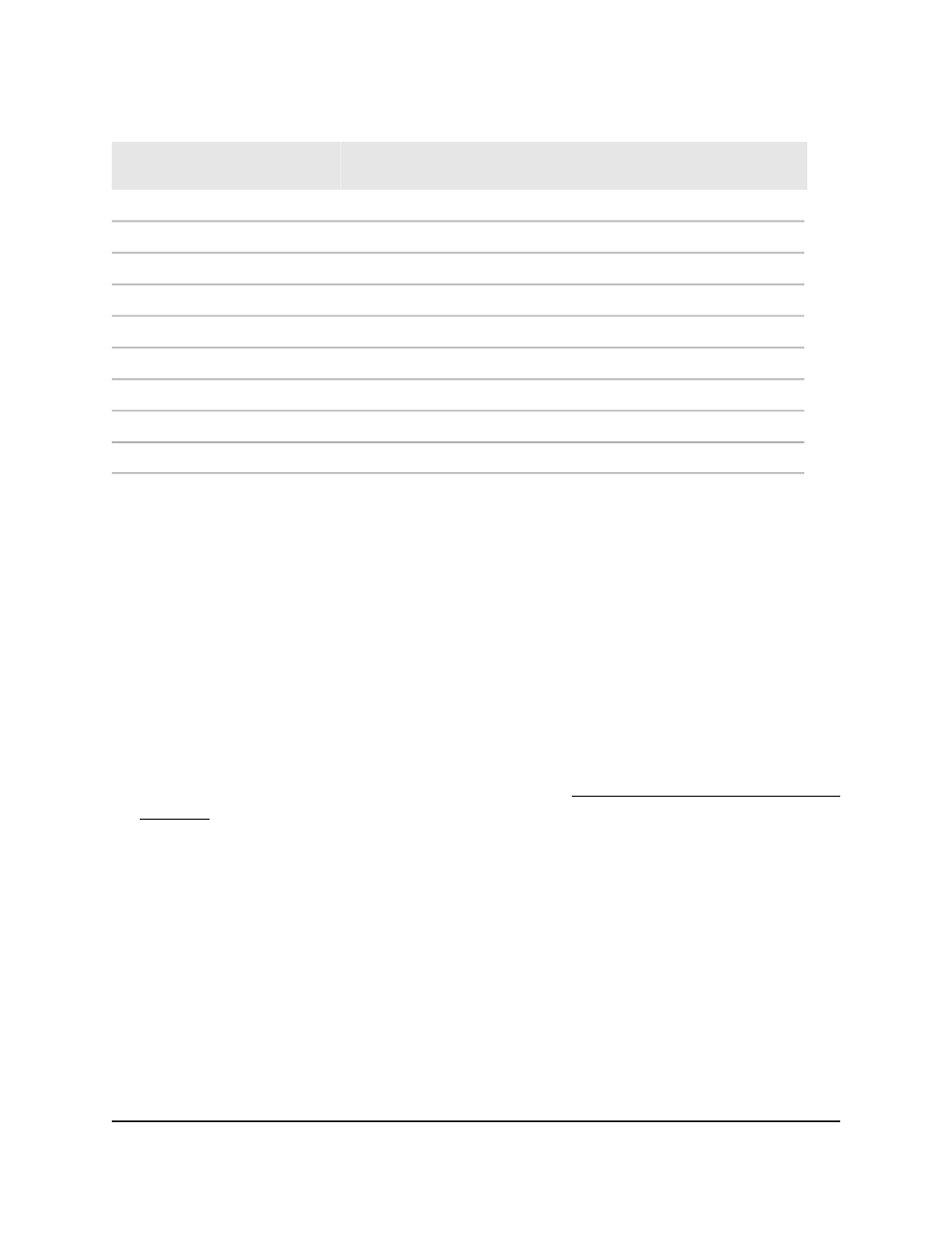
Table 42. PoE classes and PoE power allocations
Power Delivered to
the PD
Maximum Power
Reserved for the PD
Class Description
Compatible PoE
Standard
Device
Class
0.44W–15.8W
15.4W
Default power (full)
PoE, PoE+, and PoE++
0
0.44W–3.84W
4.0W
Very low power
PoE, PoE+, and PoE++
1
3.84W–7.2W
7.0W
Low power
PoE, PoE+, and PoE++
2
6.49W–15.9W
15.4W
Mid power
PoE, PoE+, and PoE++
3
12.95W–30.8W
30.0W
High power
PoE+ and PoE++
4
25.5W–47.0W
45.0W
Ultra high power
PoE++
5
51.0W–64.4W
90.0W
Ultra high power
PoE++
6
62.0W–81.1W
75.0W
Ultra high power
PoE++
7
71.0W–96.5W
90.0W
Ultra high power
PoE++
8
Set the PoE system usage threshold and
power management mode
You can configure a threshold for the PoE usage level at which a trap is sent and you
can set the power management mode that the switch uses to deliver power to the
requesting powered devices (PDs).
To set the PoE system usage threshold and power management mode:
1. Launch a web browser.
2. In the address field of your web browser, enter the IP address of the switch.
If you do not know the IP address of the switch, see Log in to the main UI with a web
browser on page 27 and the subsections.
The login page displays.
3. Click the Main UI Login button.
The main UI login page displays in a new tab.
4. Enter admin as the user name, enter your local device password, and click the Login
button.
The first time that you log in, no password is required. However, you then must
specify a local device password to use each subsequent time that you log in.
The System Information page displays.
5. Select System > PoE > Basic > PoE Configuration.
The PoE Configuration page displays.
Main User Manual
168
Configure Switch System
Information
Fully Managed Switches M4350 Series Main User Manual