Required hardware, Power up the board & view the xcvr eye – Altera High-Speed Development Kit, Stratix GX Edition User Manual
Page 25
Altera Corporation
Quartus II Version 3.0
3–3
Board Setup
Required Hardware
Required
Hardware
To power up the Stratix GX development board, you need the hardware
listed in Table 3–2. See “Development Kit Contents” on page 2–1 for a list
of items provided in the kit.
Power Up the
Board & View
the XCVR Eye
Perform the following steps to power up the Stratix GX development
board. You will set switches on the board so that the Stratix GX device
displays the transceiver (XCVR) eye in an oscilloscope.
1
Before you attempt to power up the board, make sure that you
have the equipment listed in Table 3–2.
1.
Set switch SW3 to off (middle position).
2.
Connect one end of the ATX power supply to J31 and the other end
to a power outlet.
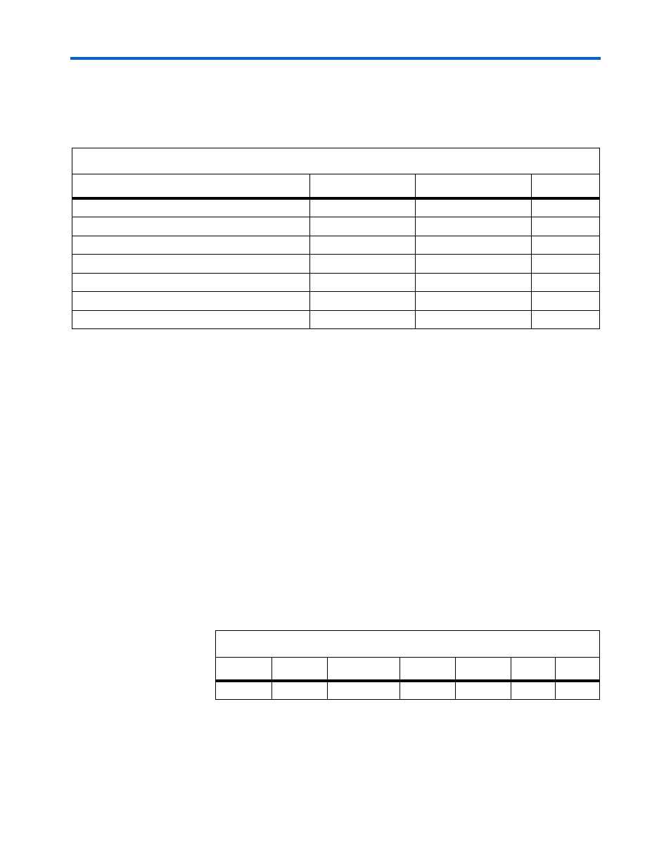
3.
Set the Stratix GX device switches as shown in Table 3–3. These
settings display the XCVR eye.
4.
Set switch SW3 to the on position (all of the way up). All of the
board LEDs illuminate.
Table 3–2. Required Equipment
Hardware
Manufacturer
Part Number
Quantity
Stratix GX Development Board
Altera
1
ATX Power Supply
Sparkle Power
FSP250-60GTA
1
Programming Cable
Altera
ByteBlaster II
1
SMA DC Block
(1)
Any
2
SMA 20-dB 50-
Ω Attenuator
(1)
Any
1
High-Speed Digital Sampling Oscillocope
(1)
,
(2)
Tektronix
CSA8000
1
3-Foot SMA Cable
(1)
Any
3
Note:
(1)
This item is required to view the XCVR eye.
(2)
You can also use other oscilloscopes.
Table 3–3. Stratix GX XCVR Eye Switches Settings
SW1
SW2
SW4
SW5
SW8
J48
J90
YES
NO
EPC16
STD
000 X
X