Altera High-Speed Development Kit, Stratix GX Edition User Manual
Page 52
5–8
Quartus II Version 3.0
Altera Corporation
Set Up the Board
High-Speed Development Kit, Stratix GX Edition User Guide
12. Attach the one end of the parallel cable to the PC’s parallel port if it
is not already attached.
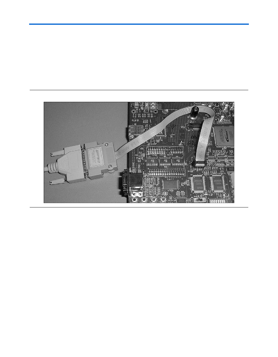
13. Connect one end of the ByteBlaster II cable to the parallel cable.
14. Connect the other end of the ByteBlaster II cable to the JTAG header
(J87) on the Stratix GX development board, as shown in Figure 5–12.
Align the red edge of the cable with pin 1.
Figure 5–12. Attach the ByteBlaster II Cable
15. Move the power selection switch (SW3) to the middle position (off).
16. Attach the main power cable from the ATX supply to the power
connector (J31) on the board.
17. Set the Stratix bypass (SW1) and Stratix GX bypass (SW2) switches
to NO.
18. Set the configuration switch (SW4) to PS_HDR as shown in