Stratix gx hm-zd (spi-4.2) functional description – Altera High-Speed Development Kit, Stratix GX Edition User Manual
Page 95
Altera Corporation
Quartus II Version 3.0
7–13
Diagnostic Test Details
Standard Tests
The loopback card feeds the serial data back to the receive inputs on the
Stratix GX device. The data is converted back into parallel form by the
receive LVDS megafunction. Because the design uses the Stratix GX DPA
feature, the receive data byte alignment may not be correct. Therefore, the
data is sent through a byte alignment and synchronization detection
block. This block looks for the synchronization pattern (the first word of
the PRBS sequence) in the data stream. When it finds the pattern, the data
is shifted as needed and the data valid is asserted. This assertion triggers
the start of an expected value PRBS generator. The two data streams are
sent to a comparator to generate a match signal on a per channel basis. If
all channels match, the match LED illuminates.
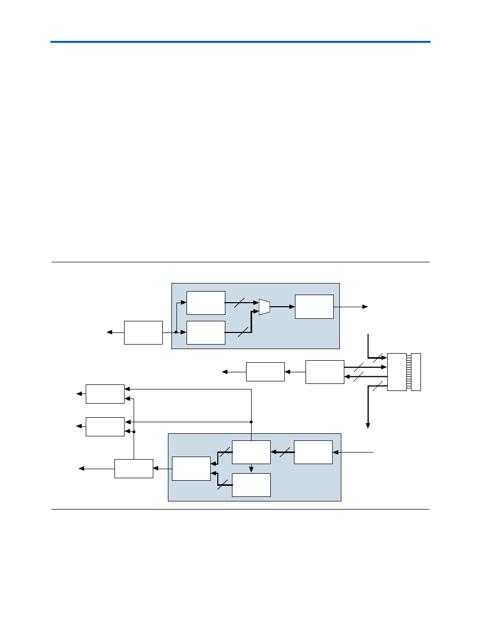
Stratix GX HM-Zd (SPI-4.2) Functional Description
Figure 7–7 shows the Stratix GX HM-Zd (SPI-4.2) logic diagram for the
Stratix GX device. Figure 7–8 shows the Quartus II top-level BDF.
1
Open the BDF in the Quartus II software to view greater detail.
Figure 7–7. HM-Zd (SPI-4.2) Logic Diagram
HM-Zd
Connector
J108
HM-Zd
Loopback
Card
Control
Signal
Logic
3
3
36
36
Control Match
Register
Control Match
LED
ALTLVDS
RX W/ DPA
Data
Aligner
Comparator
Receive Channel (x17)
8
8
8
Match
Register
Data Valid
Error
Register
Error
Counter
Data Valid
PRBS
Generator
7-Segment
Display
Error LED
Match LED
ALTLVDS
TX
Transmit Channel (x17)
8
Start/Stop
8
8-Bit
Counter
PRBS
Generator
Pattern
Generator