Stratix gx-to-stratix bridge, Stratix gx-to-stratix bridge test overview – Altera High-Speed Development Kit, Stratix GX Edition User Manual
Page 88
7–6
Quartus II Version 3.0
Altera Corporation
Standard Tests
High-Speed Development Kit, Stratix GX Edition User Guide
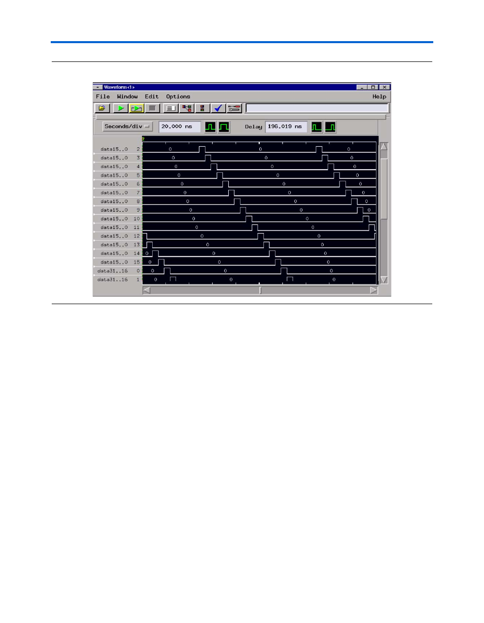
Figure 7–3. 20-Pin Logic Analyzer Screenshot
Stratix GX-to-Stratix Bridge
This section describes the Stratix GX-to-Stratix Bridge test. Refer to
“Stratix GX-to-Stratix Bridge” on page 5–12 for information on how to
perform the test.
Stratix GX-to-Stratix Bridge Test Overview
In this test, data is transmitted from the Stratix GX device to the Stratix
device and back. The Stratix GX pushbutton switches control data
transmission (start and stop) and reset the circuit. The Stratix GX LEDs
indicate the start of transmission, the reception of the synchronizing
signal, the confirmation that correct data was received, and the reset
condition.
The design uses channel 0 to indicate transmission status, start, and stop.
The other channels use this information to perform byte alignment and
begin data validation. The accuracy required for proper functioning is
+/- .5 of the unit interval (1.2 ns at the maximum data rate).