Altera High-Speed Development Kit, Stratix GX Edition User Manual
Page 96
7–14
Quartus II Version 3.0
Altera Corporation
Standard Tests
High-Speed Development Kit, Stratix GX Edition User Guide
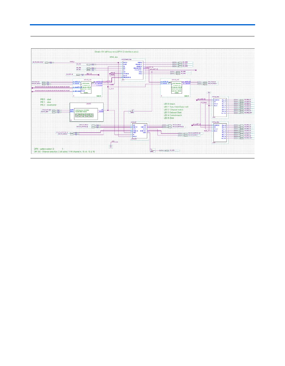
Figure 7–8. HM-Zd (SPI-4.2) Top-Levl BDF
The system clock is generated by an enhanced PLL using the on-board
33.33 MHz crystal as the reference. The PLL generates a 125-MHz clock to
run all of the data generation logic and serve as the reference for the
LVDS transmitter on the Stratix GX device.
The transmit PRBS generator is constructed with eight 5-bit linear
feedback shift registers. The output is taken from the MSB of each shift
register. The initial seed value is 8’h47. When the enable (start) signal is
high the generator outputs a 31-word sequence that repeats until
stopped. On reset the seed value is initialized into all registers. This
generator is used to generate the data stream used to exercise the system.
Each transmit channel has its own PRBS generator.
DPA technology requires a training pattern to be sent prior to the start of
data transmission. In this design, an 8-bit counter and a fixed pattern
generator create the training pattern. When you press the start button, the
counter starts and the fixed pattern transmits. When the counter reaches
256, a start signal is sent to the PRBS generator and the output multiplexer
switches over to the PRBS data.
The data from the PRBS generators is sent to the LVDS transmit block
created using the Altera MegaWizard Plug-In Manager. The
megafunction is configured as 17 channels running at 1,000 Mbps with a
clock rate of 125 MHz. The signals are sent to the HM-Zd connector and
looped back to the Stratix GX device. The high-speed control channel is
treated as any other data channel.