Edge detection, Control logic, Led decode logic – Altera High-Speed Development Kit, Stratix GX Edition User Manual
Page 85: Two shift registers
Advertising
Altera Corporation
Quartus II Version 3.0
7–3
Diagnostic Test Details
Standard Tests
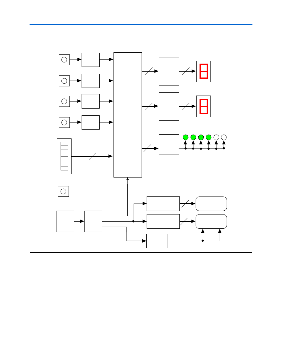
Figure 7–1. User I/O Block Diagram
The design is divided into several modules that monitor the inputs,
generate the control signals, and drive the LEDs and logic analyzer
outputs:
■
Edge detection
■
Control logic
■
LED decode logic
■
Two shift registers
8
8
Control
Logic
7-Segment
Decoder
7-Segment
Decoder
LED
Decoder
PB0
PB1
PB2
PB3
User LEDs
Dipswitches
8
3
4
4
20-Bit Shift Register
32-Bit Shift Register
Divide by 2
20-Pin
Header
Mictor
Connector
PLL
20
32
Mictor Clocks
33 MHz
200 MHz
400 MHz
Reset
33-MHz
Crystal
Oscillator
Edge
Detector
Edge
Detector
Edge
Detector
Edge
Detector
Advertising