IDK MSD-54 Series Command Guide User Manual
Page 135
MSD-54 Series Users Guide (Command Guide)
135
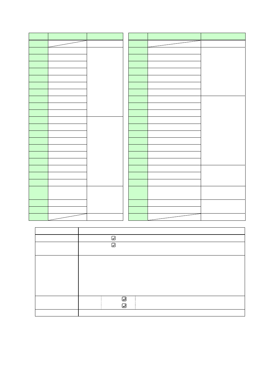
[Table 3.3.16f] MSD-5404: Factory default of Tally output
Pin
Description
Function
Pin
Description
Function
1
+5
V
26
+5
V
2 OUT1-IN1
Selecting input
channel of
OUT1
27 OUT3-IN4
Selecting
input
channel of OUT3
3 OUT1-IN2
28 OUT3-IN5
4 OUT1-IN3
29 OUT3-IN6
5 OUT1-IN4
30 OUT3-IN7
6 OUT1-IN5
31 OUT3-IN8
7 OUT1-IN6
32 OUT3-IN9
8 OUT1-IN7
33 OUT3-OFF
9 OUT1-IN8
34 OUT4-IN1
Selecting
input
channel of OUT4
10 OUT1-IN9
35 OUT4-IN2
11 OUT1-OFF
36 OUT4-IN3
12 OUT2-IN1
Selecting input
channel of
OUT2
37 OUT4-IN4
13 OUT2-IN2
38 OUT4-IN5
14 OUT2-IN3
39 OUT4-IN6
15 OUT2-IN4
40 OUT4-IN7
16 OUT2-IN5
41 OUT4-IN8
17 OUT2-IN6
42 OUT4-IN9
18 OUT2-IN7
43 OUT4-OFF
19 OUT2-IN8
44 SWITCHING–V&A
Selecting channel
switching mode
20 OUT2-IN9
45 SWITCHING–VIDEO
21 OUT2-OFF
46 SWITCHING–AUDIO
22 OUT3-IN1 Selecting input
channel of
OUT3
47 PARALLEL
LOCK
Locking parallel
input
23 OUT3-IN2
48 NOT
USE
Not assigned
24 OUT3-IN3
49 NOT
USE
25
GND
50
GND
@TDE
Initialize Tally output feature assignments
Command format
@TDE, mode
Return value
format
@TDE, mode
Parameter
mode
: Initialization mode
0 = FACTORY DEFAULT (For factory defaults, see Table 3.3.15c to Table
3.3.15f)
1 = ALL CLEAR (All pins have no assignment after initialization)
2 = Tally->PARALLEL COPY (The same setting as the Tally output
connector)
Example Send
Receive
@TDE,0
@TDE,0
Initialize parallel input functions to factory default.
Terminated normally.
Related info.
8.15.2 Feature initialization