Configuration procedure, Verification – H3C Technologies H3C SecBlade NetStream Cards User Manual
Page 108
93
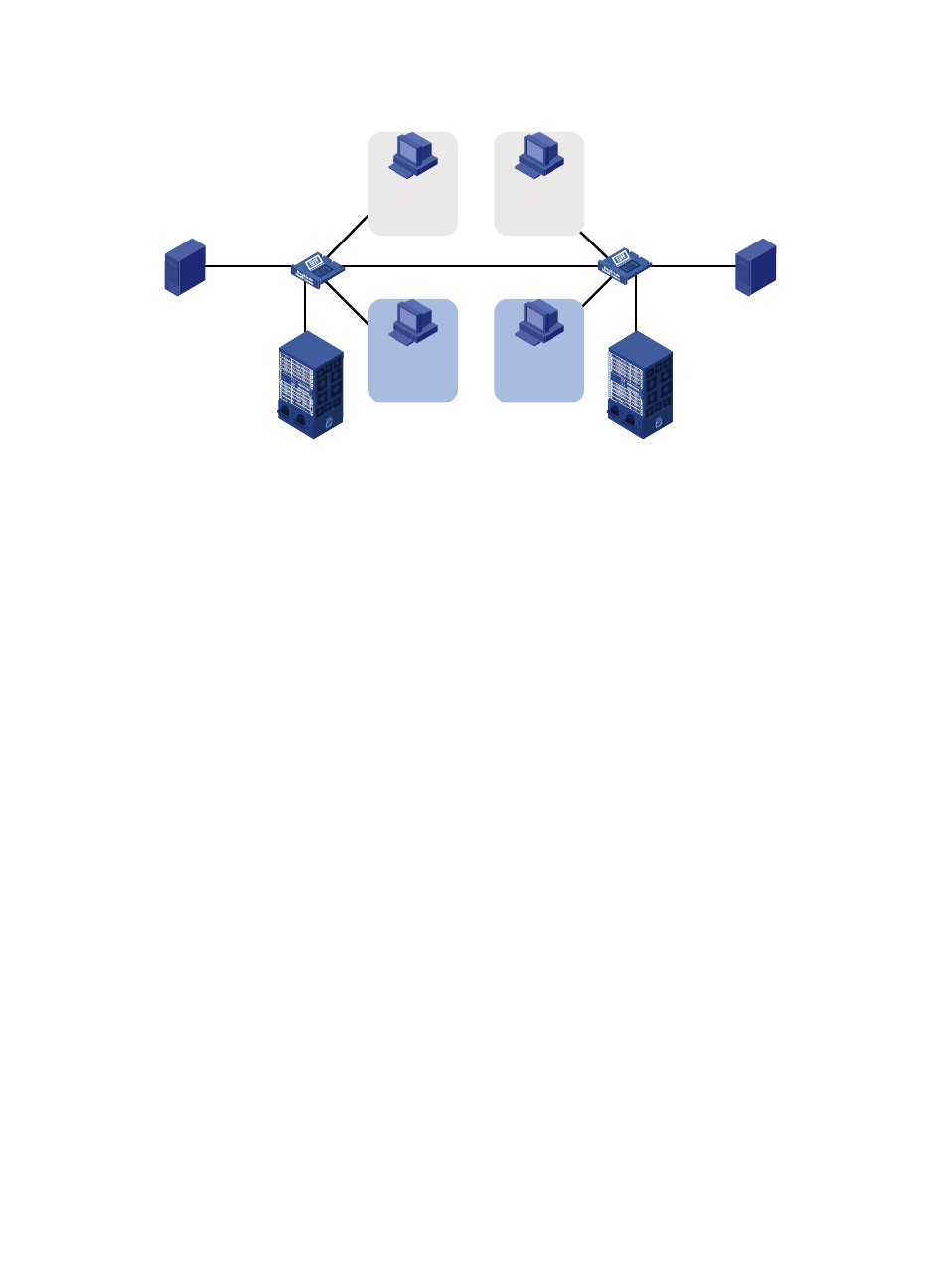
Figure 31 Network diagram for port-based VLAN configuration
Configuration procedure
1.
Configuration on SecBlade A
# Create VLAN 100, and assign port GigabitEthernet 0/2 to VLAN 100.
<SecBladeA> system-view
[SecBladeA] vlan 100
[SecBladeA-vlan100] port gigabitethernet 0/2
[SecBladeA-vlan100] quit
# Create VLAN 200, and assign port GigabitEthernet 0/3 to VLAN 200.
[SecBladeA] vlan 200
[SecBladeA-vlan200] port gigabitethernet 0/3
[SecBladeA-vlan200] quit
# Configure port GigabitEthernet 0/4 as a trunk port, and assign it to VLANs 100 and 200, enabling
GigabitEthernet 0/4 to forward traffic of VLANs 100 and 200 to SecBlade B.
[SecBladeA] interface gigabitethernet 0/4
[SecBladeA-GigabitEthernet0/4] port link-type trunk
[SecBladeA-GigabitEthernet0/4] port trunk permit vlan 100 200
Please wait... Done.
2.
Configure SecBlade B as you configure SecBlade A.
3.
Configure Host A and Host C to be on the same IP subnet. For example, 192.168.100.0/24.
Configure Host B and Host D to be on the same IP subnet. For example, 192.168.200.0/24.
Verification
1.
Host A and Host C and ping each other successfully, but they both fail to ping Host B. Host B and
Host D and ping each other successfully, but they both fail to ping Host A.
2.
Check whether the configuration is successful by displaying relevant VLAN information.
# Display information about VLANs 100 and 200 on SecBlade A.
[SecBladeA-GigabitEthernet0/4] display vlan 100
VLAN ID: 100
GE0/3
GE0/3
GE0/2
SecBlade A
GE0/2
GE0/4
GE0/4
SecBlade B
Host A
VLAN 100
Host C
VLAN 100
Host B
VLAN 200
Host D
VLAN 200
NSC
NSC