Configuration procedure, Network requirements – H3C Technologies H3C SecBlade NetStream Cards User Manual
Page 140
125
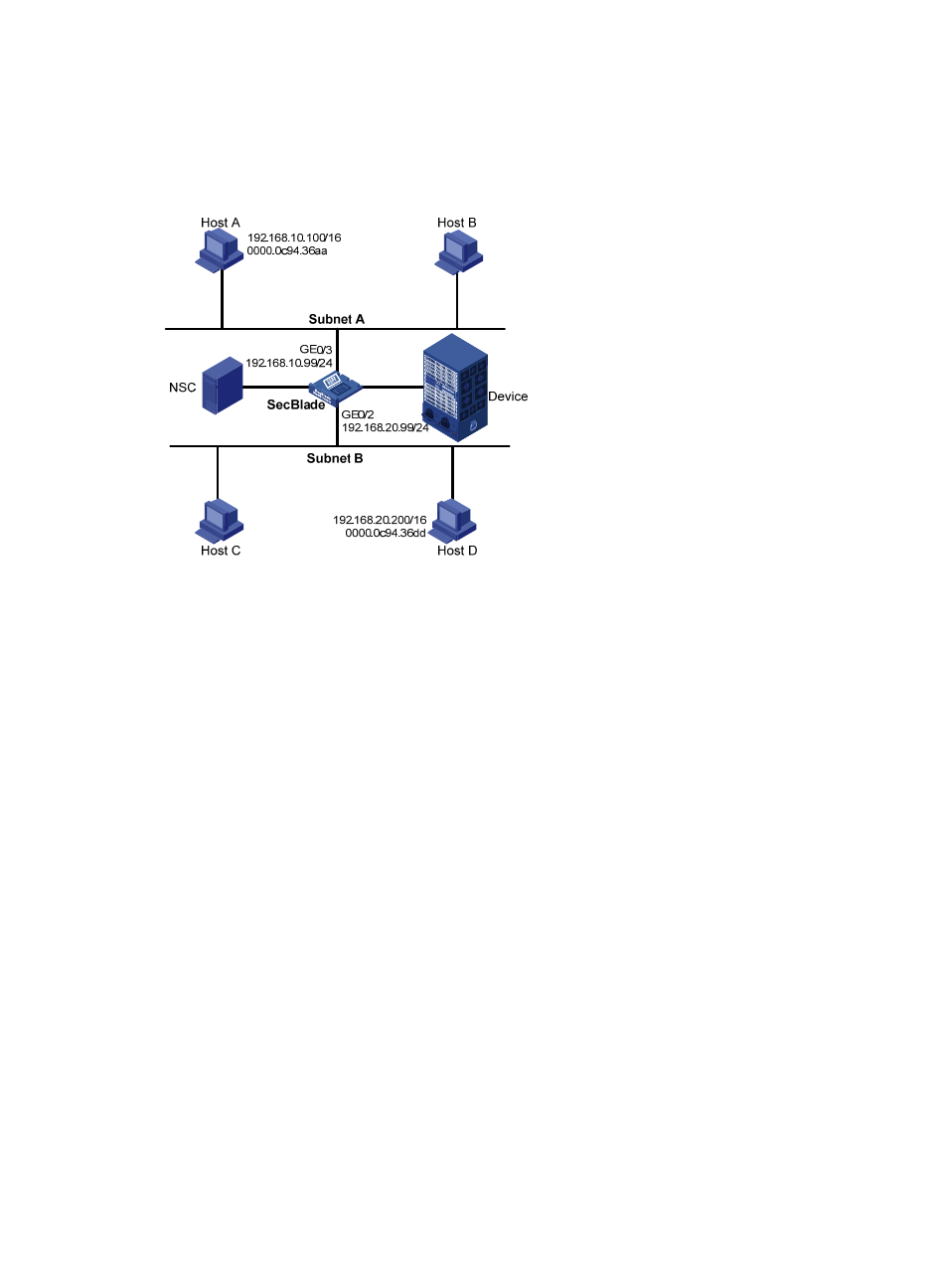
to the same network 192.168.0.0/16), but are located on different subnets. As a result, Host D cannot
receive or respond to any ARP request from Host A.
You must configure proxy ARP on the SecBlade to enable communication between Host A and Host D.
Figure 42 Network diagram for proxy ARP
Configuration procedure
# Specify the IP address of interface GigabitEthernet 0/3.
<SecBlade> system-view
[SecBlade] interface gigabitethernet 0/3
[SecBlade-GigabitEthernet0/3] ip address 192.168.10.99 255.255.255.0
# Enable proxy ARP on interface GigabitEthernet 0/3.
[SecBlade-GigabitEthernet0/3] proxy-arp enable
[SecBlade-GigabitEthernet0/3] quit
# Specify the IP address of interface GigabitEthernet 0/2.
[SecBlade] interface gigabitethernet 0/2
[SecBlade-GigabitEthernet0/2] ip address 192.168.20.99 255.255.255.0
# Enable proxy ARP on interface GigabitEthernet 0/2.
[SecBlade-GigabitEthernet0/2] proxy-arp enable
[SecBlade-GigabitEthernet0/2] quit
After completing preceding configurations, use the ping command to verify the connectivity between
Host A and Host D.
Local proxy ARP configuration example in case of port isolation
Network requirements
As shown in
, Host A and Host B belong to the same VLAN, and connect to Switch’s interfaces
Ethernet 1/3 and Ethernet 1/1. Switch connects to the SecBlade via Ethernet 1/2.