Measurement Computing Analyzer488 User Manual
Page 37
Section 2
Getting Started
2.15
Example #1 Simple trigger word ma
tch
Match Word = LAG10, Match Count
= 1, Trigger Delay = 0,
Post Count = 32767 and Trigger C
omplete Action is Stop
Record
and
Trigger
Enabled
Disar
Recor
and
Trigg
Word
Match
Trigger
Point
Buffer Location
0
32k
16K
8K
24k
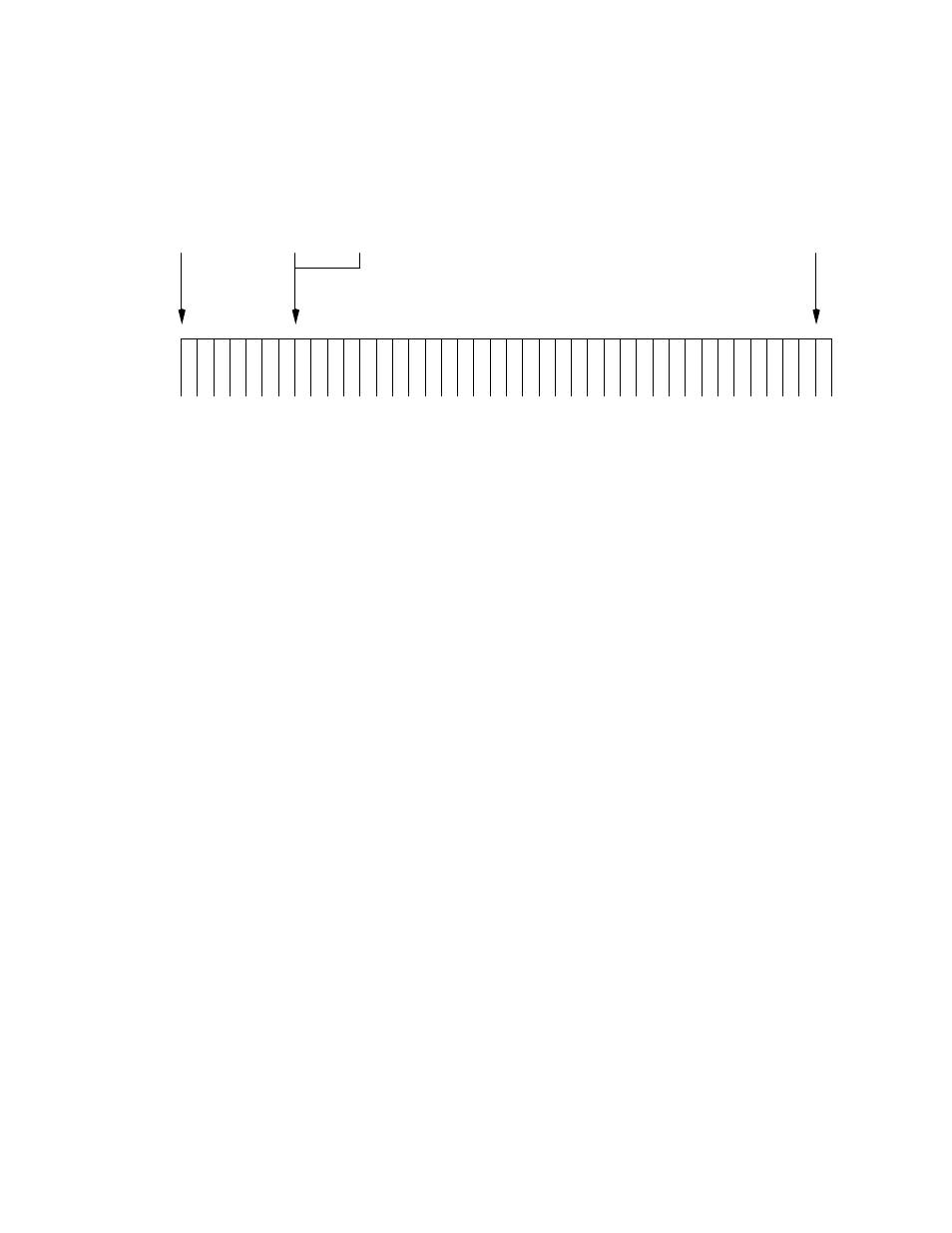
For the diagram shown above, the trigger event was defined as follows:
Match Word = LAG10 (Listen Address Group 10), Match Count =
1,Trigger Delay = 0, Post Count = 32767, and Trigger Complete Action =
Stop.
Once the trigger event was defined, recording and triggering were enabled.
The Analyzer488 began recording bus transactions, comparing each event
with the defined match word. As soon as the match word was found, the
Analyzer488 began counting and recording bus events until 32767 events
were recorded. At that time, recording was disabled. The diagram shows
that the event marked as the trigger point is stored in location 0 and the last
event recorded is stored in location 32767.