Serial controller, 1 introduction, 2 description – Measurement Computing Analyzer488 User Manual
Page 95: 3 serial interface
Section 4
Serial Controller
4.1
Serial Controller
4.1 Introduction
This section contains a detailed explanation of the Serial Controller Mode of
operation of the Analyzer488 IEEE 488 Bus Analyzer. The following paragraphs
contain a description of the Serial Controller Mode, information regarding setup,
configuration, an explanation of how to use the Analyzer488 as a serial controller, and
a detailed explanation of all the commands.
4.2 Description
When in the Serial Controller Mode, a serial host computer or terminal may
control the Analyzer488 through a serial port. Once the Analyzer488 is attached to a
computer and the IEEE 488 bus, it becomes a full-featured IEEE 488 bus controller.
The Analyzer488 may be operated as a High Level System controller or as a Low
Level System Controller. High Level Controller mode allows control of the IEEE 488
bus using High Level commands. Low Level Controller mode allows direct control
over all data and bus management lines using an alternative set of commands. The
Analyzer488 can record bus events and send the recorded data back to the host
computer. Triggering may be used to stop the recording of bus data. The
Analyzer488 front panel keyboard can be read and messages can be sent to the front
panel 20 character display.
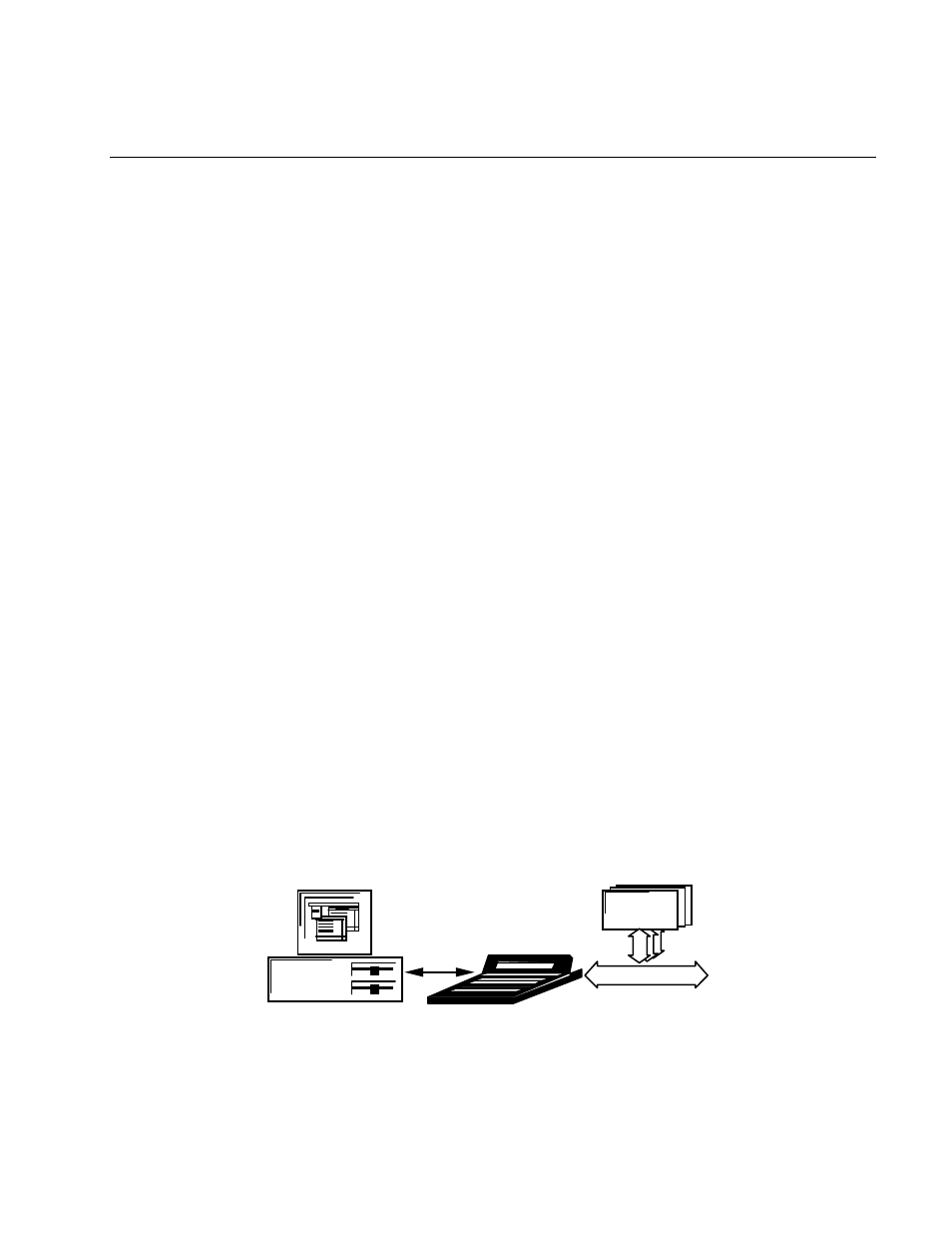
4.3 Serial Interface
To set up the Analyzer488 for use as a serial controller, connect it to the host
computer through the RS-232 connectors and to the IEEE 488 bus through the IEEE
488 bus connector on the rear panel.
IBM PC or
Compatible
Up to 14 IEEE devices
IEEE
Devices
IEEE
Analyzer488
RS-232