Measurement Computing Analyzer488 User Manual
Page 45
Advertising
Section 2
Getting Started
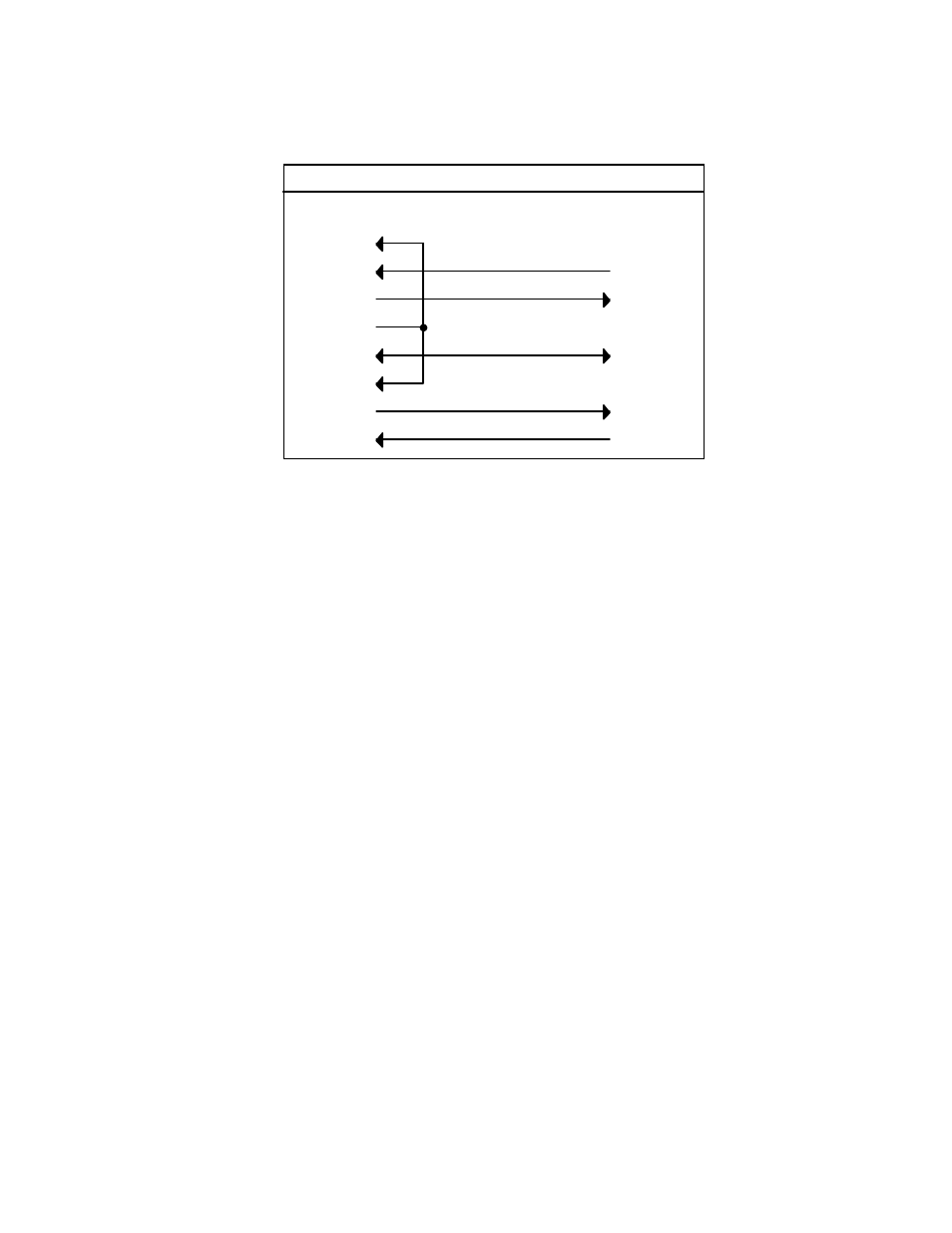
2.23
IBM AT to Analyzer488 Wiring Diagram
8
7
6
4
1
2
3
5
2
3
5
-RxD
-TxD
Gnd
-RxD
DCD
Gnd
-TxD
DB-9 Female
8
CTS
RTS
7
RTS
CTS
DSR
DTR
IBM AT to Analyzer488
DB-9 Female
Note: Standard AT 9 Pin to 25 Pin adapter cables are not wired as shown above and will
not work with the Analyzer488. Order IOtech Part Number CA-47.
WARNING
The Analyzer488 makes its earth ground
connection through the serial interface cable. It
should only be connected to IEEE bus devices
after being first connected to the host. Failure to
do so may allow the Analyzer488 to float to a
bus device test voltage. This could result in
damage to the interface, personal injury or
death.
Advertising
See also other documents in the category Measurement Computing Hardware:
- ACC-300 (7 pages)
- AI-EXP32 (20 pages)
- AI-EXP48 (19 pages)
- BTH-1208LS (30 pages)
- 6K-ERB08 (32 pages)
- BTH-1208LS Quick Start (4 pages)
- 6K-SSR-RACK08 (33 pages)
- BTH-1208LS-OEM (27 pages)
- CB-COM-Digital (68 pages)
- CB-7018 (68 pages)
- CB-7000 Utilities (44 pages)
- CB-7080D (74 pages)
- CB-COM-7033 (44 pages)
- CB-COM-7017 (72 pages)
- CB-COM-7024 (76 pages)
- CB-NAP-7000P (36 pages)
- CIO-DAC02/16 (16 pages)
- CIO-DAC02 (18 pages)
- CB-NAP-7000D (56 pages)
- CIO-DAC16-I (16 pages)
- CIO-DAC16/16 (20 pages)
- CIO-DAS08 (21 pages)
- CIO-DAC16 (20 pages)
- CIO-DAS08/JR (16 pages)
- CIO-DAS08/JR/16 (14 pages)
- CIO-DAS08/JR-AO (16 pages)
- CIO-DAS08-AOM (32 pages)
- CIO-DAS08-PGM (28 pages)
- CIO-DAS16/330 (34 pages)
- CIO-DAS48-I (17 pages)
- CIO-DAS16/M1 (38 pages)
- CIO-DAS48-PGA (18 pages)
- CIO-DAS800 (20 pages)
- CIO-DAS802/16 (22 pages)
- CIO-DAS6402/16 (40 pages)
- CIO-DAS-TEMP (20 pages)
- CIO-DDA06/16 (18 pages)
- CIO-DDA06/JR (17 pages)
- CIO-DIO24H (20 pages)
- CIO-DIO24/CTR3 (21 pages)
- CIO-DI192 (24 pages)
- CIO-DDA06 (21 pages)
- CIO-DIO48 (19 pages)
- CIO-DO192H (16 pages)
- CIO-DIO192 (20 pages)