Front panel operation, 1 introduction, 2 description – Measurement Computing Analyzer488 User Manual
Page 47: Analyzer488
Section 3
Front Panel Operation
3.1
Front Panel Operation
3.1 Introduction
This section contains a detailed explanation of the front panel operation
of the Analyzer488 IEEE 488 Bus Analyzer. It contains information
regarding setup, configuration, an explanation of how to use the front panel,
and a detailed description of all the keys and LED indicators.
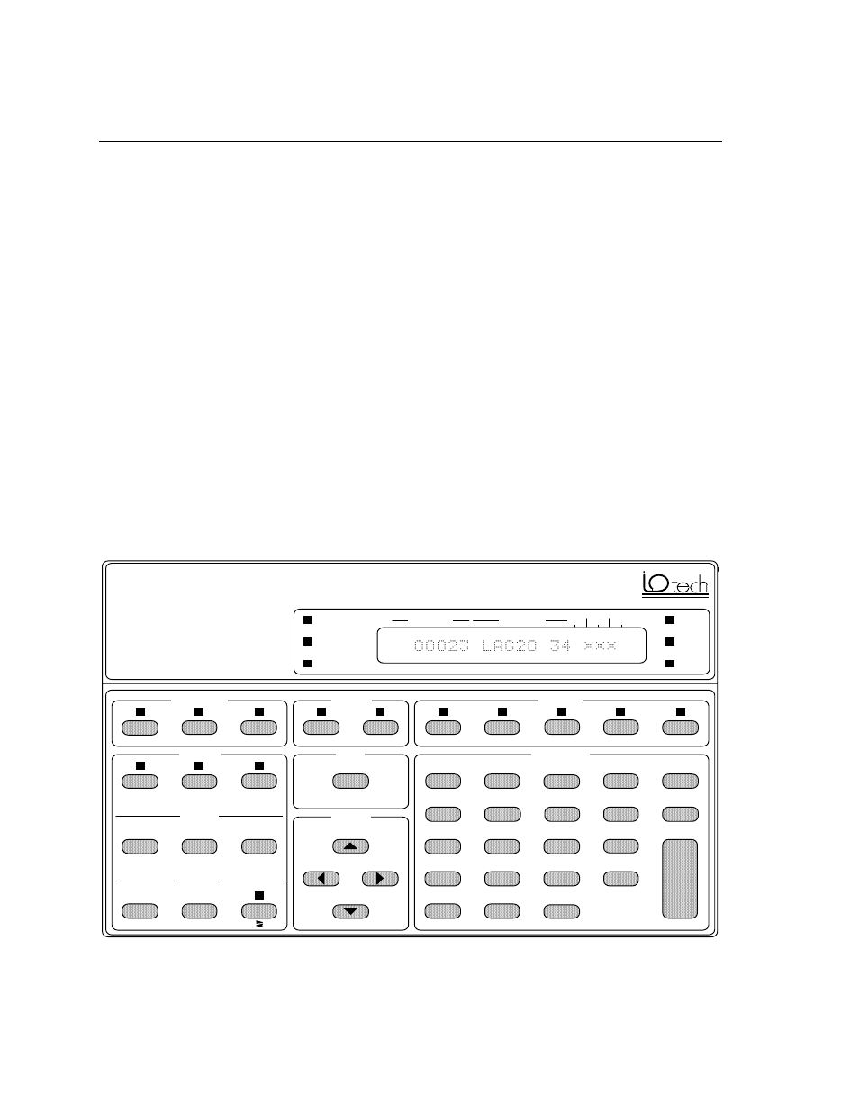
3.2 Description
Front panel operation of the Analyzer488 provides simple, portable,
bench-top access to all of the Analyzer488's features. Two display modes,
bus display mode and memory view mode, show the state of the IEEE 488
bus or the contents of record memory. The front panel display shows bus
messages and bus data in either hexadecimal and ASCII format or in binary
format. Front panel LED indicators show bus signal states and Analyzer488
states at a glance. Command keys, menu keys, and edit keys provide
functions to monitor, record, and analyze bus activity.
RATE
NONE
ERASE
ZERO
SET REL
+TRIGGER
-TRIGGER
FIND
DISPLAY
MEASURE
HEX
BIN
HANDSHAKE
MEMORY
SEARCH
TRIGGER
SOURCE
SHIFT
CURSOR
CONTROL
DATA ENTRY
SRQ
IFC
REN
ATN
BUS
MEMORY
RECORD
NRFD
NDAC
DAV
EOI
LSB
LOCATION
MESSAGE
Analyzer488
IEEE 488 Bus Analyzer
FAST
SLOW
STEP
LISTEN
TALK
EOI
ATN
SRQ
REN
IFC
EXIT
D
ENTER
E
3
C
B
5
6
2
F
+/-
SAVE
HELP
0
1
4
NEXT
LAST
FIRST
STAT
SETUP
ARM
ESC
A
8
9
7
VIEW
REC
REL