Measurement Computing Analyzer488 User Manual
Page 39
Section 2
Getting Started
2.17
Arm
Record
and
Trigger
Example # 3 Counted trigger word
match with Delay
Match Word = LAG10, Match Count =
2, Trigger Delay = 32768,
Post Trigger Count = 32768 and Tri
gger Complete Action is Step
Buffer Location
0
32k
16K
8K
24k
Trigger
Match
Trigger
Match
Trigger
Point
Delay
Finished
Delay
Started
Disarm
Trigge
and
Set Ste
Handsh
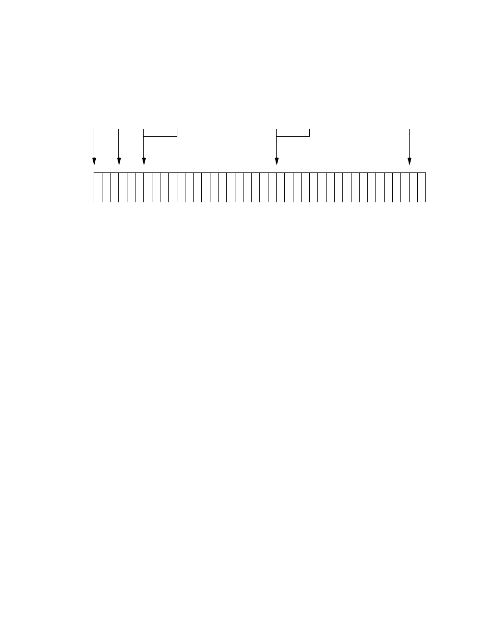
For the diagram shown above, the trigger event was defined as follows:
Match Word = LAG10 (Listen Address Group 10), Match Count =
2,Trigger Delay = 32768, Post Count = 32768, and Trigger Complete
Action = Step.
Once the trigger event was defined, recording and triggering were then
enabled. The Analyzer488 began recording bus transactions, comparing
each event with the defined match word. Each time the match word was
found, the Match Count was decremented. When the Match Count was
decremented to zero, the Analyzer488 began counting and recording bus
events until 32768 events were counted. At that time, the trigger event was
marked and recording continued until 32768 events were recorded. At that
time,recording was still enabled and the handshake circuitry was set to step
mode, halting bus transactions until a step command was issued. The
diagram shows that the event marked as the trigger point is stored at
location 0. The last event recorded in this case will be the last event
recorded before recording was disabled by issuing a command or by a
keypress.