3 serial cable wiring diagrams – Measurement Computing Analyzer488 User Manual
Page 44
Section 2
Getting Started
2.22
handshake is selected, the RTS line will be permanently driven
active high.
CTS
Clear To Send - Input - Pin 8
The CTS input is used as a hardware handshake line to prevent the
Analyzer488 from transmitting serial data when the RS-232 host is
not ready to accept it. When RTS/CTS handshake is selected on
the internal switches, the Analyzer488 will not transmit data out -
TxD
while this line is un-asserted (low). If the RS-232 host is not
capable of driving this line it can be connected to the Vtest
output (Pin 6) of the Analyzer488. If XON/XOFF handshake is
selected, the CTS line is not tested to determine if it can transmit
data.
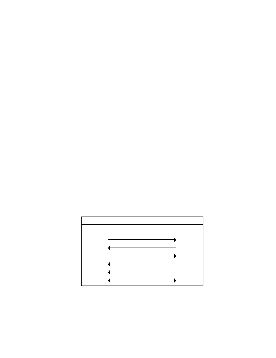
2.5.3 Serial Cable Wiring Diagrams
If a cable was not purchased with the interface, the following diagrams
will be helpful in making your own cable. Simple soldering skills and an
attention to detail will ensure successful construction. Refer to the Serial
Controller section of this manual for complete information on using the
Analyzer488 with serial devices.
IBM PC/XT/PS2 to Analyzer488 Wiring Diagram
2
3
4
5
6
2
3
8
7
4
-RxD
-TxD
CTS
RTS
DTR
-RxD
-TxD
DSR
CTS
RTS
DB-25 Female
7
5
Gnd
Gnd
IBM PC/XT/PS2 to Analyzer488
DB-9 Female