Vdl-m2 – Wavecom W74PC V8.7.0 User Manual
Page 268
258
Transmission Modes
WAVECOM Decoder W74PC, W-PCI/e, W-CODE, W-CLOUD Manual V8.7.0
In most systems the accuracy of the single frequencies has to be within +1/-1.5% of the nominal value.
Decoding the selective calls is started by clicking on a system. If transmission and system selection con-
form, the call sign is displayed on the monitor. In the Options menu a Time stamp function can be ena-
bled to add date and time to each call.
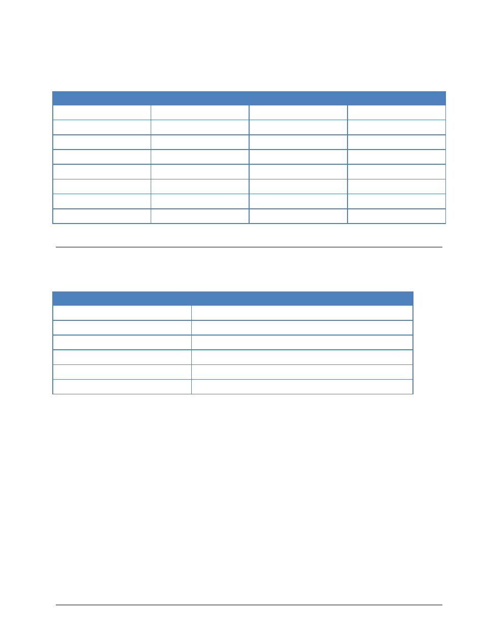
Tone Allocation
Digit
Hz
Digit
Hz
0
2280
8
1520
1
370
9
1860
2
450
A
2000
3
550
B
2100
4
675
C
2200
5
825
D
2300
6
1010
E
2400
7
1240
Tone duration: 100 ms.
VDL-M2
VHF digital link (VDL) Mode 2 is an air-ground data link specified in the ICAO documents “Annex 10 Vol-
ume III - Communication Systems” and” Manual on VHF Digital Link (VDL) Mode 2”.
Frequency range
VHF
Frquency range
VHF, 136.975 MHz (std. transmission frequency)
Operation modes
CSMA
Modulation
D8PSK
Symbol rate
31.5 kBd
Receiver settings
BW = 15-30 kHz
Input(s)
IF
VDL-M2 uses D8PSK (Differentially encoded 8-Phase Shift Keying) modulation scheme operating at a bit
rate of 31.5 kbps in a 25 kHz frequency band. The data is transmitted in the form of short bursts. The
maximum number of data bits at a single packet is 217 -1 bits, which corresponds to a packet length of
approximately 4 seconds.
Each packet carries a header field, which contains a 48 bits synchronization sequence and a packet length
field. The packet length field is protected with a (25, 20) block code, and the remaining data bits are pro-
tected with a systematic fixed-length Reed Solomon (255, 249) 28-ary code.
Channel access is achieved using the carrier sense multiple access (CSMA) algorithm and the data link
service sublayer uses the aviation VHF link control (AVLC) protocol. AVLC is an extension of the HDLC
standard which is specified by the following ISO documents: ISO 3309, ISO 4335, ISO 7809, and ISO
8885.
The AVLC packets start and end with a special flag byte (0x7E) and include a 9 bytes long AVLC header af-
ter the start flag and 2 bytes long CRC field before the end flag. The header contains the 24-bit ICAO air-
craft/ground station addresses of the sending and receiving terminals and one byte link control field indi-
cating the type of the packet, e.g., INFO, Receive Ready (RR), Exchange Identity (XID), TEST, and Selec-
tive Reject (SREJ).
In HEX output mode, the whole AVLC packet is printed bytewise as hex.
In ITA5-US mode the AVLC frame types and 24-bit ICAO aircraft / ground station addresses are decoded
and printed. For INFO frames, the data field is decoded correspondingly if it is an ACARS packet, and is