Patch mode – MultiDyne ACI-2058 User Manual
Page 75
Chapter 4: Connections
A54-3000-100 A
36
A
PCON
, Inc.
4.1.1.
Patch Mode
The Patch mode you select results in the following:
Blade letter
Displays the blade position within the chassis.
Blade labels use letters and start at the bottom. Port labels use
numbers prefaced by blade letter, and start at the left. For more
information, see
Blade power LED
The LED color indicates blade status:
• Green: This blade’s power is on.
• Gray: This blade’s power is off.
The LED is also a link which, when clicked, displays the Blade
Power screen. For details about this screen, see
Field
Description
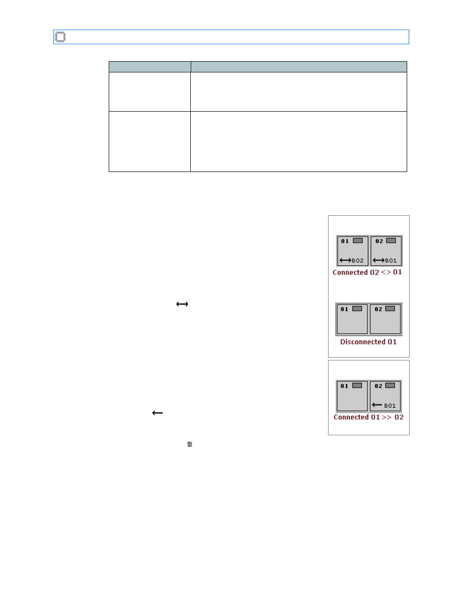
•
Duplex (normal): Connected ports each transmit and receive.
When you select port A01, then select port A02, the ports
connect and each port transmits or receives simultaneously.
The label of the first selected port displays in the Patched Port
field of the second selected port, and the label of the second
selected port displays in the Patched Port field of the first
selected port
This bi-directional connection is indicated at the bottom of the
screen with the “
” symbol.
When you select either port, then click Trash, both ports
disconnect.
If you change to Simplex mode, then select a port and click
Trash, the port you selected disconnects.
•
Simplex (advanced): Connected ports either transmit or receive.
When you select port A01, then select port A02, port A01 sends
data to port A02. The label of the first selected port displays in
the Patched Port field of the second selected port. This single-
direction connection is indicated at the bottom of the screen
with the “
” symbol.
When you select port A01, then click Trash, the connection
between A01 and A02 remains unchanged. When you select
port A02, then click
TRASH
, the ports disconnect.
Duplex
Connecting
Disconnecting
Simplex
Connecting