4 logic blocks, 1 tsi - time slot interchanger, Figure 9-3 – Artesyn ARTM-831X Installation and Use (June 2014) User Manual
Page 163: Tsi structure diagram, Tsi fpga
TSI FPGA
ARTM-831X Installation and Use (6806800M76E)
163
All signals are active high unless denoted by a trailing _N symbol. Differential signals are
denoted by a trailing _P (plus) or _M (minus) symbol.
9.4
Logic Blocks
9.4.1
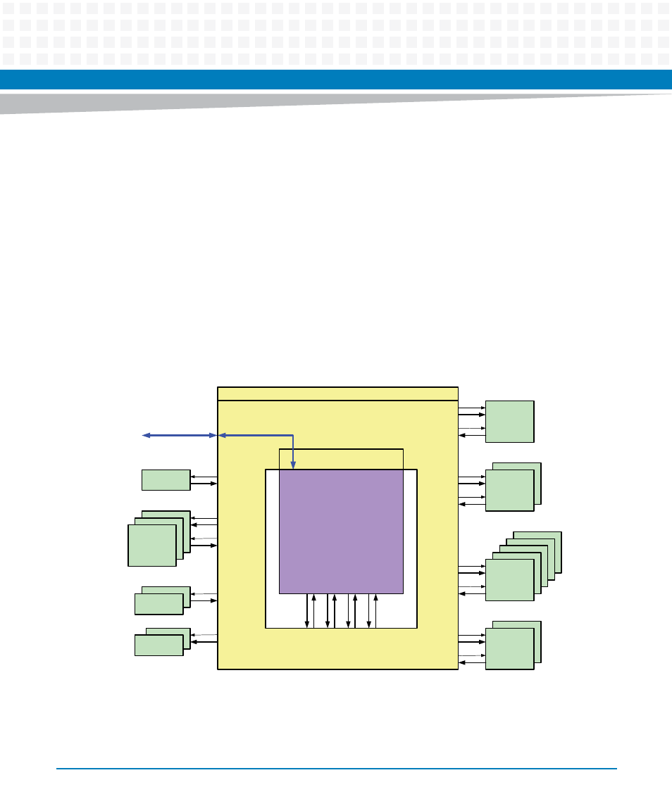
TSI - Time Slot Interchanger
The Times-Slot-Interchanger connects 65536 input speech channels to 65536 output speech
channels. Any output can be connected to any input at any time determined by the entries in
the connection memory. Each speech channel holds 8bit data information in a 125μs time
frame.
The TSI Slot Counter is the main counter from which all addresses, memory selects, address-
and data-paths, read and write signals for the speech- and connection memories are derived.
Figure 9-3
TSI structure diagram
MUX
CM
(connection memory )
SM
(speech memory)
DSP pool
via
SERDES
HMVIP
channel 0
TOH
gen
e
ra
te
e
n
ab
le
co
n
n
e
c
t b
u
s
gen
e
ra
te
e
n
ab
le
co
n
n
e
c
t b
u
s
TP
Comparator
TP
Generator
SBI
0 .. 2
0 .. 1
0 .. 1
0 .. 1
0 .. 5
0 .. 1
TSI Channel Supervisor
TSI Slot Counter
8 bit TDM
with enable
for each connction
4 x 8 bit
TDM
TSI
wishbone bus
interface
di
re
ct
ly
c
o
nn
ect
e
d
to
in
p
u
t/o
u
tp
u
t
li
n
e
Gr8