Functional description – Artesyn ARTM-831X Installation and Use (June 2014) User Manual
Page 92
Functional Description
ARTM-831X Installation and Use (6806800M76E)
92
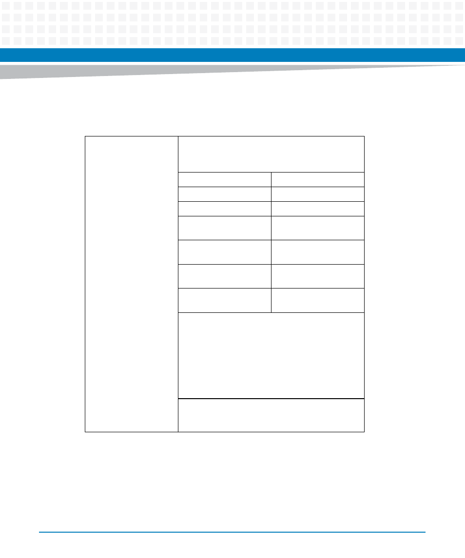
On a connected patch panel the ID_PRSNT signal requires an individual pull-down resistor
(Rpp) for patch panel type identification. A RTM side pull resistor of 825 Ohm and 5V rail result
in discrimination levels according to the description below:
ID_PRSNT
Dual purpose pin, described in (i) and (ii) below:
(i) Identify to the RTM the type of breakout panel
fitted, determined by voltage level on this pin
Voltage
Function
5V
No patch panel present
<5V
Patch panel present
4V
E1 patch panel present
(Rpp=3k3)
3V
DS3 patch panel present
(Rpp=1k2)
2V
DS1 patch panel present
(Rpp=560R)
0V
Patch panel present and
pushbutton pressed
(ii) To identify which RTM the breakout panel is
connected to:
The user presses and holds a button on the breakout
panel and a blue LED lights next to the connected RTM
VHDCI connector.
Connected to a momentary push button on breakout
panel, normally open, when pressed ID_PRSNT pin is
connected to GND.
RTM needs a blue LED (and current limiting resistor)
located on rear panel next to each breakout VHDCI
connector.