2 connectors, 1 faceplate connectors, Table 3-2 – Artesyn ARTM-831X Installation and Use (June 2014) User Manual
Page 57: Ethernet interfaces - rj45 connector pin-out, Table 3-3, E1/t1 interface - rj45 connector pin-out, Controls, leds, and connectors
Controls, LEDs, and Connectors
ARTM-831X Installation and Use (6806800M76E)
57
3.2.2
Connectors
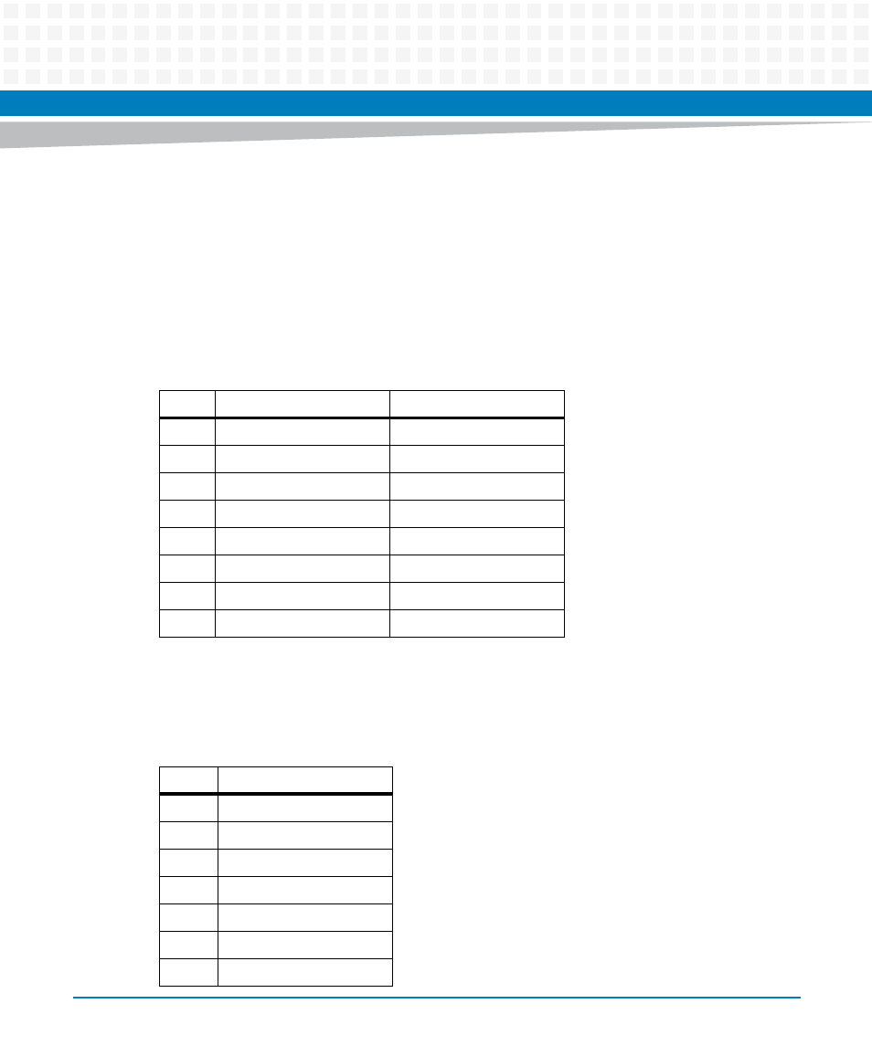
The blade provides ethernet interfaces and the BITS/SSU (E1/T1) Interface at its face plate.
3.2.2.1
Faceplate Connectors
One 1x4 low-profile, shielded RJ45 connector with integrated LED (green/yellow) is available at
the ARTM-831X face plate, providing four ports Ethernet connectivity.
Two 1x1 low-profile, shielded RJ45 connectors (w/o LED) at the ARTM-831X face plate provide
access to the 2 ports of the BITS/SSU interface.
Table 3-2 Ethernet Interfaces - RJ45 Connector Pin-out
Pin
10Base-T / 100Base-TX
1000Base-T
1
ETH_TX+
ETH_DA+
2
ETH_TX-
ETH_DA-
3
ETH_RX+
ETH_DB+
4
ETH_DC+
5
ETH_DC-
6
ETH_RX-
ETH_DB-
7
ETH_DD+
8
ETH_DD-
Table 3-3 E1/T1 Interface - RJ45 Connector Pin-out
Pin
Signal
1
E1/T1_RX+
2
E1/T1_RX-
3
NC
4
E1/T1_TX+
5
E1/T1_TX-
6
NC
7
NC