Hypertherm MicroEDGE Pro Shape Cutting Control Rev.2 User Manual
Page 128
Maintenance and diagnostics
4-32
MicroEDGE Pro
Instruction Manual 807290
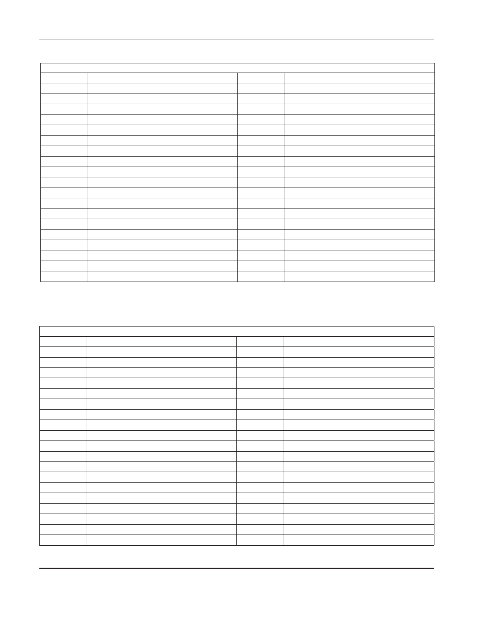
Connector j8 (12 I/o)
Pin no.
Signal
Pin no.
Signal
1
Input 1
20
Watchdog contact B
2
Input 2
21
Output 1
3
Input 3
22
Output 2
4
Input 4
23
Output 3
5
Input 5
24
Output 4
6
Input 6
25
Output 5
7
Input 7
26
Output 6
8
Input 8
27
Output 7
9
Input 9
28
Output 8
10
Input 10
29
Output 9
11
Input 11
30
Output 10
12
Input 12
31
Output 11
13
Not connected
32
Output 12
14
+24 V
33
Shield
15
+24 V
34
+24 V
16
Not connected
35
+24 V
17
Common
36
Common
18
Common
37
Common
19
Watchdog contact A
Connector j7 (Axes 1 and 2, x and y)
Pin no.
Signal
Pin no.
Signal
1
Encoder voltage
20
Analog common
2
Encoder voltage
21
Axis 1 (X), encoder B\
3
Encoder common
22
Axis 1 (X), encoder Z
4
Encoder voltage
23
Axis 2 (Y), encoder Z\
5
Axis 2 (Y), encoder A
24
Axis 1 (X), enable in
6
Encoder common
25
Axis 1 (X), enable out
7
Ground
26
Axis 2 (Y), enable in
8
Encoder common
27
Axis 2 (Y), enable out
9
Axis 1 (X), encoder A
28
Axis 1 (X), encoder Z\
10
Axis 2 (Y), encoder B
29
Axis 2 (Y), reference+
11
Axis 2 (Y), encoder A\
30
Analog common
12
Ground
31
Ground
13
Ground
32
Analog common
14
Axis 1 (X), encoder A\
33
Axis 1 (X), reference+
15
Axis 1 (X), encoder B
34
Analog voltage +
16
Axis 2 (Y), encoder Z
35
Analog voltage -
17
Axis 2 (Y), encoder B\
36
Analog voltage -
18
Analog common
37
Analog voltage +
19
Ground