Thc cable specifications, Thc cable specifications -28 – Hypertherm MicroEDGE Pro Shape Cutting Control Rev.2 User Manual
Page 76
InstallatIon
2-28
MicroEDGE Pro
Instruction Manual 807290
tHC cable specifications
The following tables provide the pin-out details for the connectors on the Sensor THC amplifier, the MicroEDGE Pro
CNC, and the voltage divider board (VDC3). Use these tables to manufacture the cables that connect these devices in
your configuration.
Pin-outs for voltage divider board 3 (VDC3) connectors
Pin-out for the cable between j2 on VDC3 and tHC 1 on the CNC
j2 I/o Connector on VDC3
tHC1 Connector on the CNC
Pin no.
Signal
Pin no.
outputs
1
24 VDC common (out)
1
24 VDC Common (in)
2
+24 VDC (out)
2
Nozzle Contact Sense +
3
Nozzle contact sense (output)
3
Nozzle Contact Sense -
4
Nozzle contact enable (input)
4
Nozzle Contact Enable +
5
24 VDC common (out)
5
Nozzle Contact Enable -
6
+ Analog out
6
+ Analog in
7
- Analog out
7
- Analog in
8
Chassis ground (cable shield)
8
Hold +
9
Hold -
j3 field connector on VDC3 (black terminal strip)
Pin no.
Signal
1
EMI Ground
2
Electrode (connection to negative connection inside plasma system)
3
Work (connection to the positive connection inside the plasma system)
4
No connection
6
Ohmic contact wire connection
j1 Power connector on VDC3
Pin no.
Signal
1
120 VAC line
2
120 VAC neutral
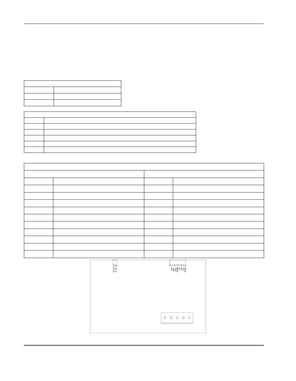
Voltage divider board (141201)
J1
J2
J3