Picopath drive/encoder connectors, Picopath drive/encoder connectors -12, Installation 2-12 – Hypertherm MicroEDGE Pro Shape Cutting Control Rev.2 User Manual
Page 60
InstallatIon
2-12
MicroEDGE Pro
Instruction Manual 807290
1
5
10
16
23
29
34
4
9
15
22
28
33
37
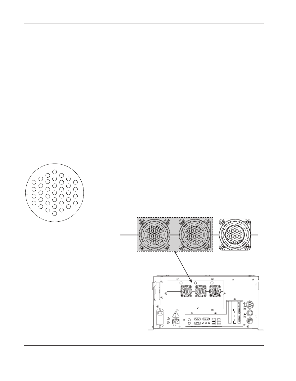
Picopath drive/encoder
connector j6 and j7
Picopath drive/encoder connectors
Picopath axis assignments are made in Phoenix software on the Machine Setups > Axis screen. For more information,
see the Phoenix Software Installation and Setup Manual.
Use the following information to create Picopath drive/encoder cables.
The Picopath drive/encoder mating connector is a 37-pin, circular connector:
• Cable connector: AMP #208472-1
• Pin contacts AMP 66099-3 (16–18 ga), AMP 66103-3 (20–24 ga)
• Cabling: Belden # 9504 or equivalent for encoder signals
• Cabling: Belden # 9501 or equivalent for drive signals
• Hypertherm kit: 228489
Notes:
• Enable individual drives for each axis for proper operation.
• Connect cable shields to the metal shell of the connector for optimum noise immunity and to keep signal commons
separate from the ground.
Picopath drive/encoder connectors
j6
z/W AxIS
DRV/ENC
j7
x/y AxIS
DRV/ENC
I/o