Hypertherm MicroEDGE Pro Shape Cutting Control Rev.2 User Manual
Page 135
Maintenance and diagnostics
MicroEDGE Pro
Instruction Manual 807290
4-39
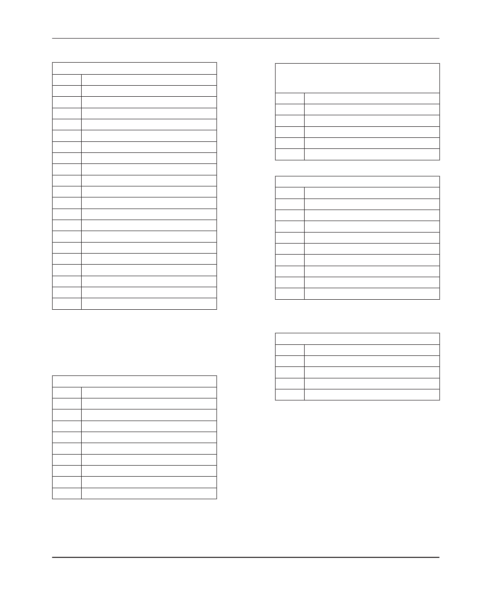
Connector j3 (
to Serial CoM3 and CoM4
)
Pin no. Signal
1
Ground
2
DR_A
3
/RXD_INA
4
TS_A
5
TXD_OUTA
6
TS_A
7
DR_A
8
Ground
9
Ground
10
Not connected
11
Ground
12
DR_B
13
/RXD_INB
14
TS_B
15
TXD_OUTB
16
TS_B
17
DR_B
18
Ground
19
Ground
20
Not connected
Connector j5 (Serial port A, CoM3)
Pin no. Signal
1
Not connected
2
Transmit A-
3
Receive A-
4
Transmit A+
5
Signal ground 1
6
Not connected
7
Receive A+
8
Not connected
9
Not connected
Connector j6
(
to motherboard on/off and
power distribution
)
Pin no. Signal
1
Field power
2
Fan
3
Ground
4
Motherboard on/off 2
5
Motherboard on/off 1
Connector j8 (Serial port B, CoM4)
Pin no. Signal
1
Not connected
2
Transmit B-
3
Receive B-
4
Transmit B+
5
Signal ground 2
6
Not connected
7
Receive B+
8
Not connected
9
Not connected
Connector j10 (to front panel on/off switch)
Pin no. Signal
1
Ground
2
12 V
3
Motherboard on/off 2
4
Motherboard on/off 1