Hypertherm MicroEDGE Pro Shape Cutting Control Rev.2 User Manual
Page 129
Advertising
Maintenance and diagnostics
MicroEDGE Pro
Instruction Manual 807290
4-33
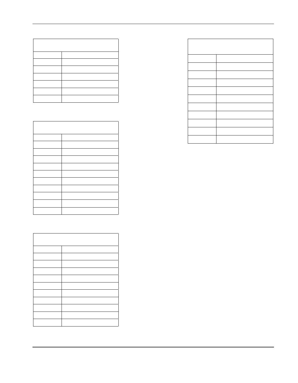
Connector j11 (to power distribution
board)
Pin no.
Signal
1
Field ground
2
+24 V
3
+5 V
4
-12 V
5
+12 V
6
Field ground
Connector j12 (jumper for 5 V encoder
sourced)
Pin no.
Signal
1
+Ve
2
+5 Vf
3
+Va
4
+12 Vf
5
-Va
6
-12 Vf
7
+24 V
8
+24 Vf
9
/Axis watchdog
10
/Axis watchdog hdr
Connector j13 (jumper for 12 V
encoders sourced)
Pin no.
Signal
1
+Ve
2
+12 Vf
3
+Va
4
+12 Vf
5
-Va
6
-12 Vf
7
+24 V
8
+24 Vf
9
/Axis watchdog
10
/Axis watchdog hdr
Connector j14 (jumper for external
encoder voltage)
Pin no.
Signal
1
+Ve
2
Not connected
3
+Va
4
Not connected
5
-Va
6
Not connected
7
+24 V
8
Not connectedf
9
/Axis watchdog
10
/Axis watchdog hdr
Advertising