Hypertherm MicroEDGE Pro Shape Cutting Control Rev.2 User Manual
Page 144
Maintenance and diagnostics
4-48
MicroEDGE Pro
Instruction Manual 807290
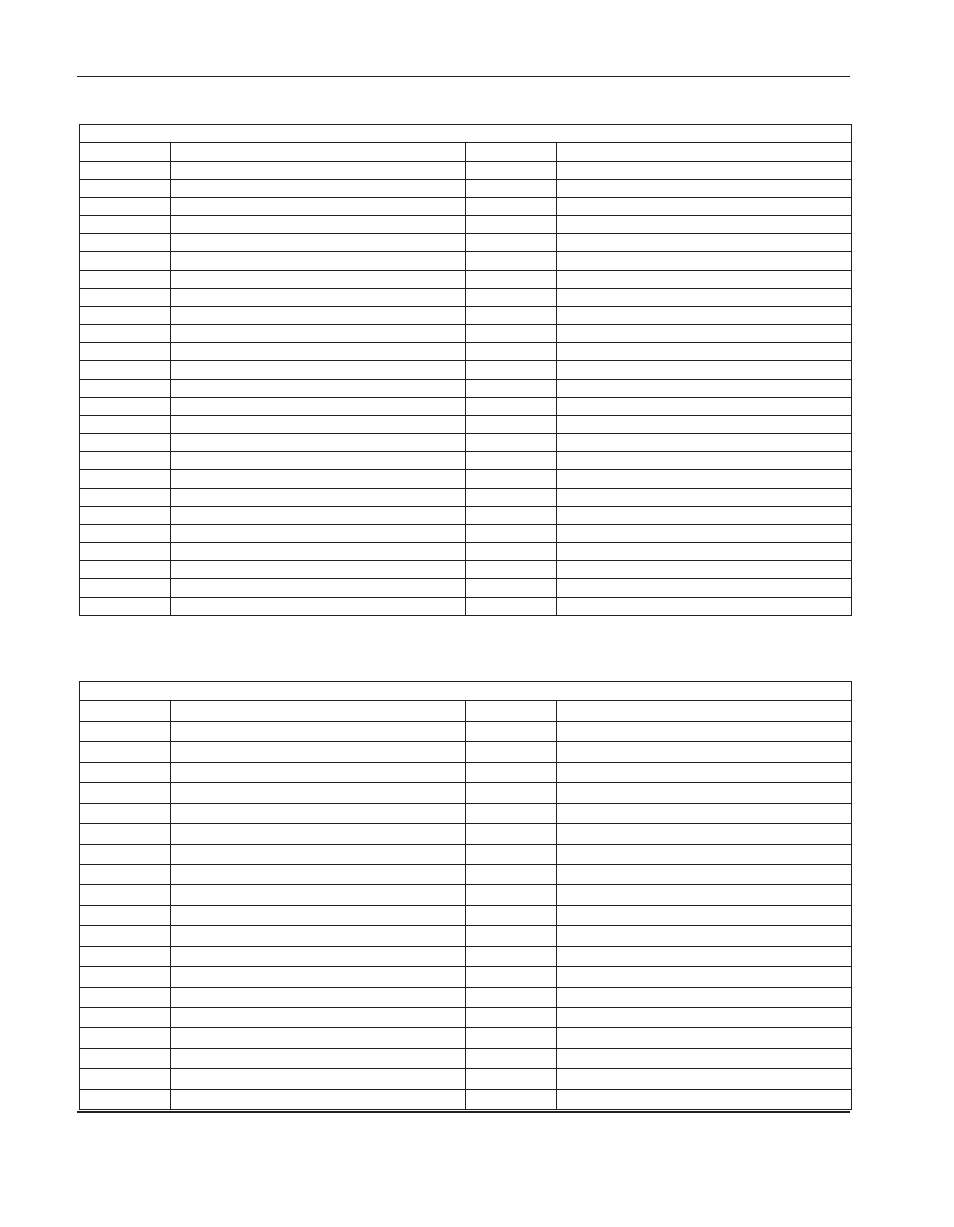
Connector j5 (I/o 1-12)
Pin no.
Signal
Pin no.
Signal
1
Input 1
26
Not connected
2
Output 1
27
Not connected
3
Input 2
28
Not connected
4
Output 2
29
Not connected
5
Input 3
30
Not connected
6
Output 3
31
Not connected
7
Input 4
32
Not connected
8
Output 4
33
Not connected
9
Input 5
34
Not connected
10
Output 5
35
Not connected
11
Input 6
36
Not connected
12
Output 6
37
Not connected
13
Input 7
38
Not connected
14
Output 7
39
Not connected
15
Input 8
40
Not connected
16
Output 8
41
Not connected
17
Input 9
42
Not connected
18
Output 9
43
Not connected
19
Input 10
44
Not connected
20
Output 10
45
Not connected
21
Input 11
46
Not connected
22
Output 11
47
Picopath ID (0=True) HyPath ID (NC=1=False)
23
Input 12
48
Not connected
24
Output 12
49
Not connected
25
Not connected
50
Ground
Connector j7 (Axes 1 and 2, x and y)
Pin no.
Signal
Pin no.
Signal
1
Encoder voltage
20
Analog common
2
Encoder voltage
21
Axis 1 (X), encoder B\
3
Encoder common
22
Axis 1 (X), encoder Z
4
Encoder voltage
23
Axis 2 (Y), encoder Z\
5
Axis 2 (Y), encoder A
24
Axis 1 (X), enable in
6
Encoder common
25
Axis 1 (X), enable out
7
Ground
26
Axis 2 (Y), enable in
8
Encoder common
27
Axis 2 (Y), enable out
9
Axis 1 (X), encoder A
28
Axis 1 (X), encoder Z\
10
Axis 2 (Y), encoder B
29
Axis 2 (Y), reference+
11
Axis 2 (Y), encoder A\
30
Analog common
12
Ground
31
Ground
13
Ground
32
Analog common
14
Axis 1 (X), encoder A\
33
Axis 1 (X), reference+
15
Axis 1 (X), encoder B
34
Analog voltage +
16
Axis 2 (Y), encoder Z
35
Analog voltage -
17
Axis 2 (Y), encoder B\
36
Analog voltage -
18
Analog common
37
Analog voltage +
19
Ground