Hypertherm MicroEDGE Pro Shape Cutting Control Rev.2 User Manual
Page 145
Maintenance and diagnostics
MicroEDGE Pro
Instruction Manual 807290
4-49
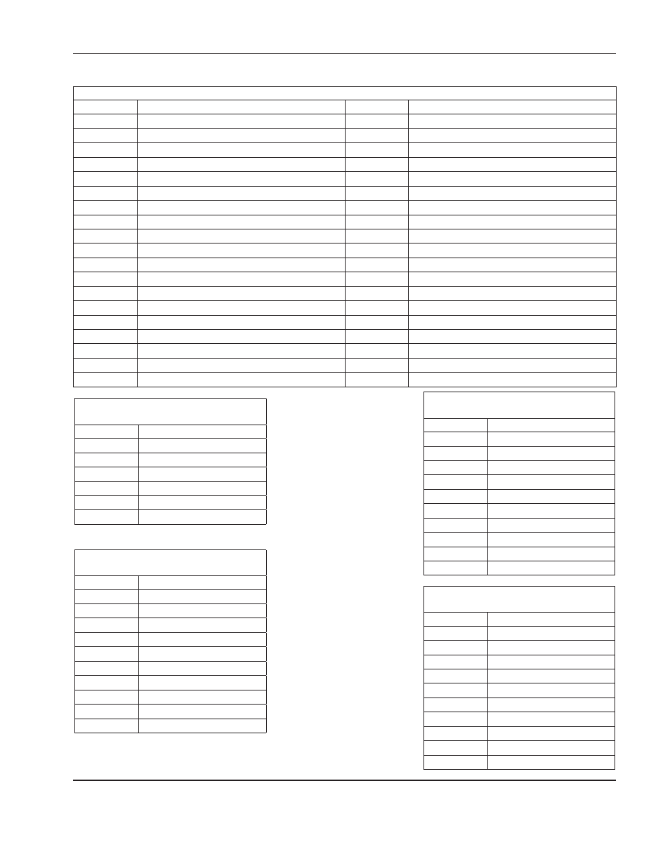
Connector j8 (12 I/o)
Pin no.
Signal
Pin no.
Signal
1
Input 1
20
Watchdog contact B
2
Input 2
21
Output 1
3
Input 3
22
Output 2
4
Input 4
23
Output 3
5
Input 5
24
Output 4
6
Input 6
25
Output 5
7
Input 7
26
Output 6
8
Input 8
27
Output 7
9
Input 9
28
Output 8
10
Input 10
29
Output 9
11
Input 11
30
Output 10
12
Input 12
31
Output 11
13
Not connected
32
Output 12
14
+24 V
33
Shield
15
+24 V
34
+24 V
16
Not connected
35
+24 V
17
Common
36
Common
18
Common
37
Common
19
Watchdog contact A
Connector j11 (to power distribution
board)
Pin no.
Signal
1
Field ground
2
+24 V
3
+5 V
4
–12 V
5
+12 V
6
Field ground
Connector j12 (jumper for 5 V encoders
sourced)
Pin no.
Signal
1
+Ve
2
+5 Vf
3
+Va
4
+12 Vf
5
-Va
6
-12 Vf
7
+24 V
8
+24 Vf
9
/Axis watchdog
10
/Axis watchdog hdr
Connector j13 (jumper for 12 V
encoders sourced)
Pin no.
Signal
1
+Ve
2
+12 Vf
3
+Va
4
+12 Vf
5
-Va
6
-12 Vf
7
+24 V
8
+24 Vf
9
/Axis watchdog
10
/Axis watchdog hdr
Connector j14 (jumper for external
encoder voltage)
Pin no.
Signal
1
+Ve
2
Not connected
3
+Va
4
Not connected
5
-Va
6
Not connected
7
+24 V
8
Not connected
9
/Axis watchdog
10
/Axis watchdog hdr