Hypertherm MicroEDGE Pro Shape Cutting Control Rev.2 User Manual
Page 74
InstallatIon
2-26
MicroEDGE Pro
Instruction Manual 807290
1
5
10
16
23
29
34
4
9
15
22
28
33
37
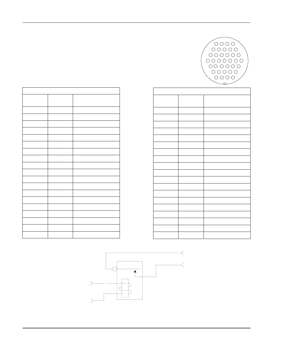
HyPath servo connectors j3, j4
Drive/Encoder pin-outs
The following illustration shows the axis-enable relay contacts for each axis on the 4-axis servo board.
HyPath 4-axis servo – axis enable output relay contacts
A
B
3
4
1
2
Relay SPST
Connector j3 (Axes 1 and 2)
Pin no.
for Axis 1
Pin no.
for Axis 2 Signal
1
20
Axis shield
2
21
Encoder +5 V out
3
22
Encoder common
4
23
Encoder +12 V out
5
24
Encoder common
6
25
Encoder +24 V out
7
26
Encoder common
8
27
Encoder Axis A
9
28
Encoder Axis A\
10
29
Encoder Axis B
11
30
Encoder Axis B\
12
31
Encoder Axis Z
13
32
Encoder Axis Z\
14
33
Axis enable A
15
34
Axis enable B
16
35
Axis servo output
17
36
Analog common
18
37
Axis shield
19
Shield
CNC
Customer
Notes:
• Z Channel is the marker pulse channel which is 1 pulse/revolution.
• Not all axes may be available. Verify how many axes are available on your CNC in the
Diagnostics > Control Information screen in Phoenix software.
Connector j4 (Axes 3 and 4)
Pin no.
for Axis 3
Pin no.
for Axis 4 Signal
1
20
Axis shield
2
21
Encoder +5 V out
3
22
Encoder common
4
23
Encoder +12 V out
5
24
Encoder common
6
25
Encoder +24 V out
7
26
Encoder common
8
27
Encoder Axis A
9
28
Encoder Axis A\
10
29
Encoder Axis B
11
30
Encoder Axis B\
12
31
Encoder Axis Z
13
32
Encoder Axis Z\
14
33
Axis enable A
15
34
Axis enable B
16
35
Axis servo output
17
36
Analog common
18
37
Axis shield
19
Shield