Grass Valley Kaleido-X v.7.80 User Manual
Page 381
373
Kaleido-X
User’s Manual
serious consequences. To avoid such problems, it is desirable to give operators access only
to those crosspoints they need, by creating logical routers.
To add a logical router
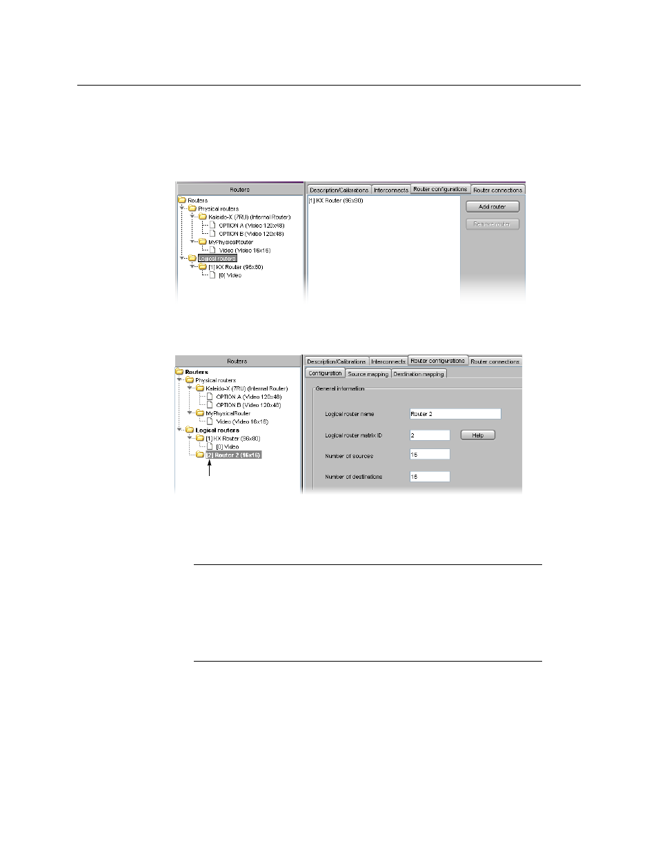
1 In the Routers list, click the Logical routers folder, and then click Add router under the
Router configurations tab.
A new sub-folder is added to the Logical routers folder. This new folder is automatically
selected, and a third-level tab bar appears under Router configurations, with the
Configuration tab selected.
2 Type a name (e.g., “SmallLogicalRouter”) in the Logical router name box. This is the
name that will appear on monitor wall in the Assign [router] input menu. Ignore the
Logical router matrix ID box for now. Type the desired number of sources and
destinations (e.g., 16 × 4).
Note:
In the case of a multiviewer systems configured with an upstream
router that has more than 288 sources, the Assign [router] input menu is not
available, and you must manage the router’s physical sources as logical
sources within the multiviewer system (see
Router sources can thus be assigned to monitor wall elements transparently,
just as sources connected directly to the multiviewer’s inputs (see
New logical router