Grass Valley Kaleido-X v.7.80 User Manual
Page 543
535
Kaleido-X
User’s Manual
• In the case of a Kaleido-X (7RU) or Kaleido-X (14RU), cards are presented in the
order they appear, from left to right when looking at the front of the chassis.
• In the case of a Kaleido-X (4RU), cards are presented in the order they appear,
starting from the top left corner down, and again from the top right corner, when
looking at the front of the chassis.
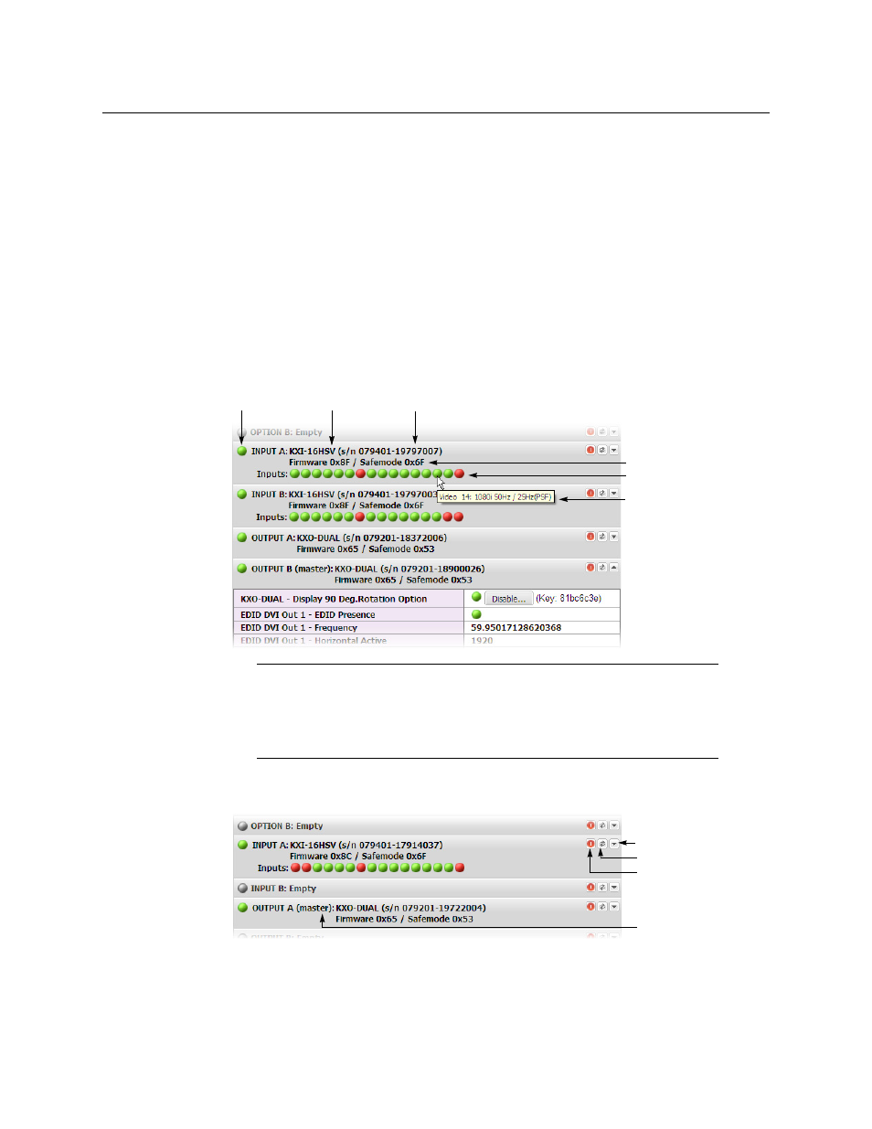
• Some heading rows may show a card type, serial number, firmware and safe mode
versions, a module status indicator, and input signal status indicators.
• The module status indicator shows whether the card (or module) is running
normally (green) or in safe mode (red).
• The signal status indicators reveals the presence of a valid input signal at the
corresponding connector.
2 Move the pointer to an input signal status indicator to view the associated signal
format.
3 Click the arrow button at the end of each heading row to view detailed information
about the associated module.
In the case of a Kaleido-X, Kaleido-MX, Kaleido-MX 4K, or Kaleido-Modular-X
multiviewer model, you can identify which output card currently assumes the software
master role (and is thus assigned the multiviewer’s IP address) by looking for the word
“master” next to the card’s identifier, for example: “OUTPUT A (master)”.
Note:
The Kaleido-X software does not distinguish between 1080PsF25 and
1080i50, and neither between 1080PsF29.97 and 1080i59.94. Both
1080PsF25 and 1080i50 are reported as 1080i50, and both 1080PsF29.97 and
1080i59.94 are reported as 1080i59.94, on the monitor wall and in XAdmin’s
Status and Options page.
Card type Serial number
Version information
Input signal status
Input signal format
Status indicator
Expand details
Refresh
Reset card
Master card status
indicator