Grass Valley Kaleido-X v.7.80 User Manual
Page 458
450
Tally Interface Devices &Timer Systems
Zodiak Production Switcher
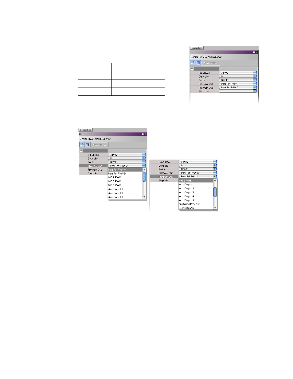
In the Properties pane, the serial communications
properties for the Zodiak device are the following,
by default:
10 Set these properties to match the values used on
the switcher.
11 Select the appropriate outputs to use for the Preview Out and Program Out tally
calculation, based on your switcher’s configuration.
The current version of the Kaleido-X software supports monitoring of one Preview
output and one Program output from any of the Zodiak switcher’s physical or internal
M/E units (Pgm-Pst PVW A, and B; M/E 1 PVW, M/E 2 PVW, M/E 3 PVW; Pgm-Pst PGM A,
and B; M/E 1 PGM, M/E 2 PGM, M/E 3 PGM), from up to 13 Aux bus outputs, or from the
additional switched preview output.
Assigning Zodiak tallies, input names, and output names to logical sources
The Zodiak contribution tally protocol provides information on up to 128 external sources,
up to 13 Aux bus outputs, and the switched preview output from the Zodiak Video
Processor Frame, in addition to the Preview and Program outputs you selected (see
Establishing serial communication between the Zodiak switcher and the multiviewer
page 448). In XEdit’s Channels/Sources tab, configure logical sources using text sources
and system tallies from the Zodiak’s serial interface. You will find these elements by
expanding the filtered system list that appears in the Tools pane.
To configure your logical sources
1 In the Channels/Sources tab, add the required number of text and alarm levels for your
purposes (see
Creating and Configuring Logical Sources
You may, for example, add one text level to monitor source labels from the Zodiak
switcher, and two alarm levels to monitor Program and Preview tallies.
Baud Rate
38400
Data Bits
8
Parity
NONE
Stop bits
1