GeoVision GV-AS2120 IP Control Panel User Manual
Page 111
Advertising
GV-AS410 / 4110 / 810 / 8110 Controller
109
5
=
4
7
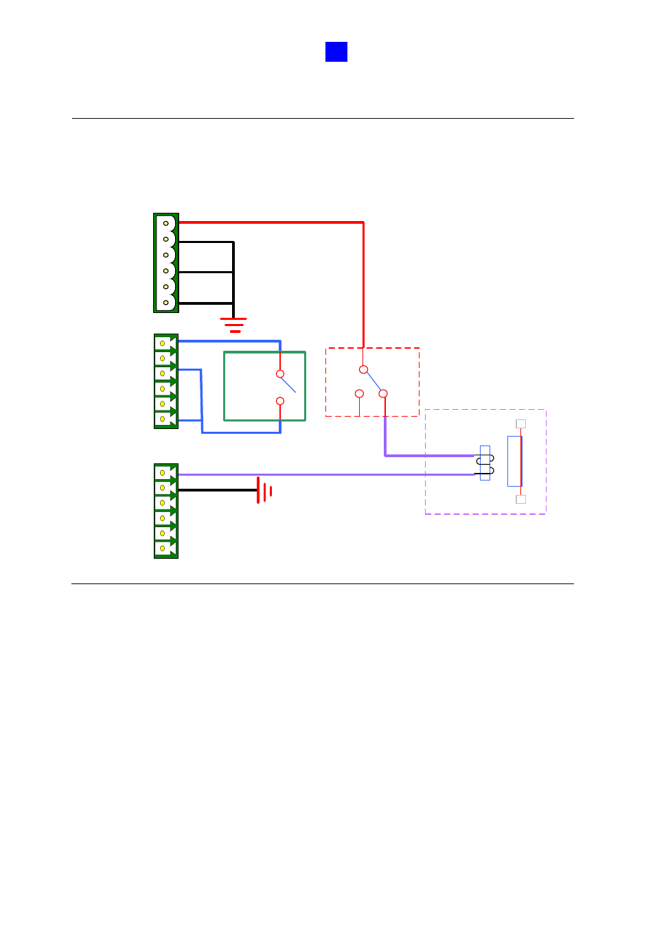
Note:
It is highly recommended that you connect the fire alarm button to the 12V power
port and electromagnetic lock directly, as the figure below shows. This enables all the
associated doors to be triggered even if your GV-AS41 / 81 series Controller behaves
abnormally when a fire condition occurs.
IN1
IN2
INCOM
IN3
IN4
INCOM
NC
COM
NO
NC
COM
NO
Power
INPUT
OUTPUT
Exit
Button
1
2
Electromagnetic
Lock
+
-
12V
GND
12V
GND
12V
GND
NC
NO
COM
Fire Alarm
Button
Advertising