3 gv-asnet overview – GeoVision GV-AS2120 IP Control Panel User Manual
Page 196
Advertising
194
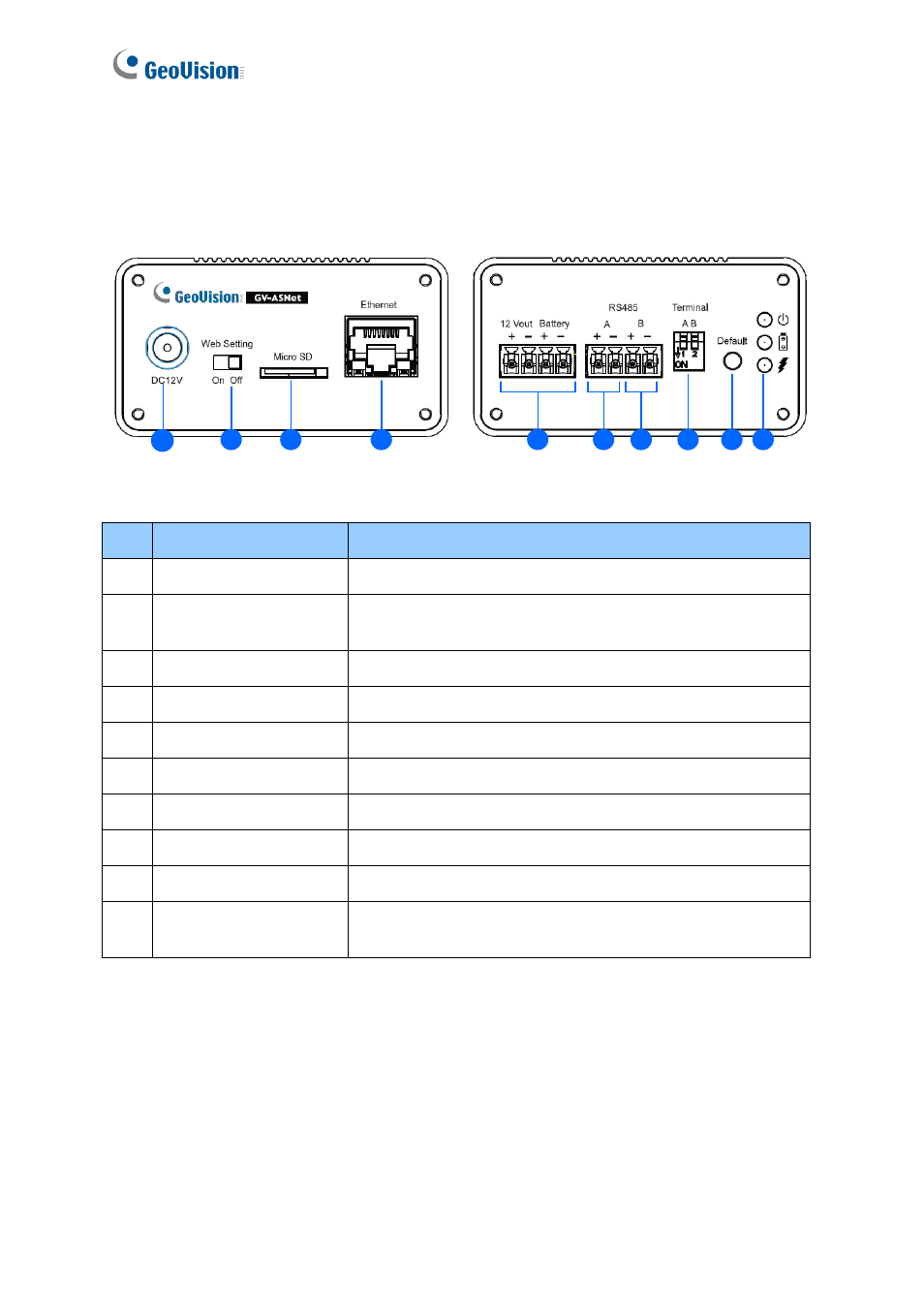
9.2.3 GV-ASNet Overview
Front View
Rear View
7
6
5
4
3
2
1
8
9
10
Figure 9-9
No.
Name
Function
1
DC Power Input (12V)
Connects to power supply.
2
Web Setting
Enables the Advanced Settings on Web interface of GV-
AS100/GV-AS110/GV-AS120.
3
Micro SD
The Micro SD slot is not functional at this point.
4
Ethernet
Connects to the network.
5
12V+/12V- Battery
Power supply for GV-AS100/GV-AS110/GV-AS120.
6
RS485A+/RS485A-
Connects to GV-AS100/GV-AS110/GV-AS120.
7
RS485B+/RS485B-
Connects to GV-Readers.
8
Terminal A/B
Enables RS-485 interface.
9
Default button
Resets all configurations to factory defaults.
10
Power LED
Shows the power source and battery charging status of the
GV-ASNet. See
9.2.4.C Other Settings
for more details.
Advertising