3 board layout, Figure 4-1 – GeoVision GV-AS2120 IP Control Panel User Manual
Page 91
Advertising
GV-AS210 / 2110 / 2120 Controller
89
4
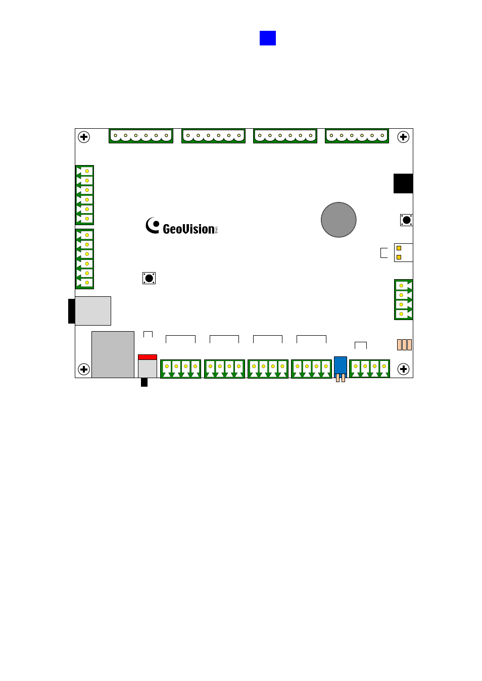
4.1.3 Board Layout
GV-AS210 / 2110
Ethernet
GV-AS210 / 2110
Micro SD
DI1
DI2
DI3
DI4
com.A
com.A
DI5
DI6
DI7
DI8
com.B
com.B
NC8
COM8
NO8
NC7
COM7
NO7
NC6
COM6
NO6
NC5
COM5
NO5
NC4
COM4
NO4
NC3
COM3
NO3
NC2
COM2
NO2
NC1
COM1
NO1
Power
Jack
Default
GND
GND
12V
12V
ON OFF
Web Setting
12V
D0
D1
GND
12V
D0
D1
GND
12V
D0
D1
GND
12V
D0
D1
GND
A+
A-
B+
B-
LED1
-3
RS-485
_A T
ERM
RS-485
_B T
ERM
Extend Read
er
Wiegand
A
Wiegand
B
Wiegand
C
Wiegand
D
LED
1:Power(R
ed
)
LED
2:Dis-C
harging(
G
re
en
)
LED
3:Charg
ing
(Yell
ow
)
1 2 3
Battery
+
_
RTC Battery
(Only available
in
GV-AS2110
)
Figure 4-1
Advertising