3 connecting output devices – GeoVision GV-AS2120 IP Control Panel User Manual
Page 97
GV-AS210 / 2110 / 2120 Controller
95
4
4.2.3 Connecting Output Devices
Up to 8 output devices can be connected to GV-AS210 / 2110 / 2120. Check if your output
device meets the following absolute maximum ratings before connecting it to outputs 1 ~ 8.
Breakdown Voltage
110V AC ~ 250V AC, 30V DC
Continuous Load Current
3A (AC), 3A (DC)
Note:
Absolute Maximum Ratings are those values beyond which damage to GV-
AS210 / 2110 / 2120 circuit board may occur. Continuous operation of GV-AS210 /
2110 / 2120 at the absolute rating level may affect the controller’s reliability.
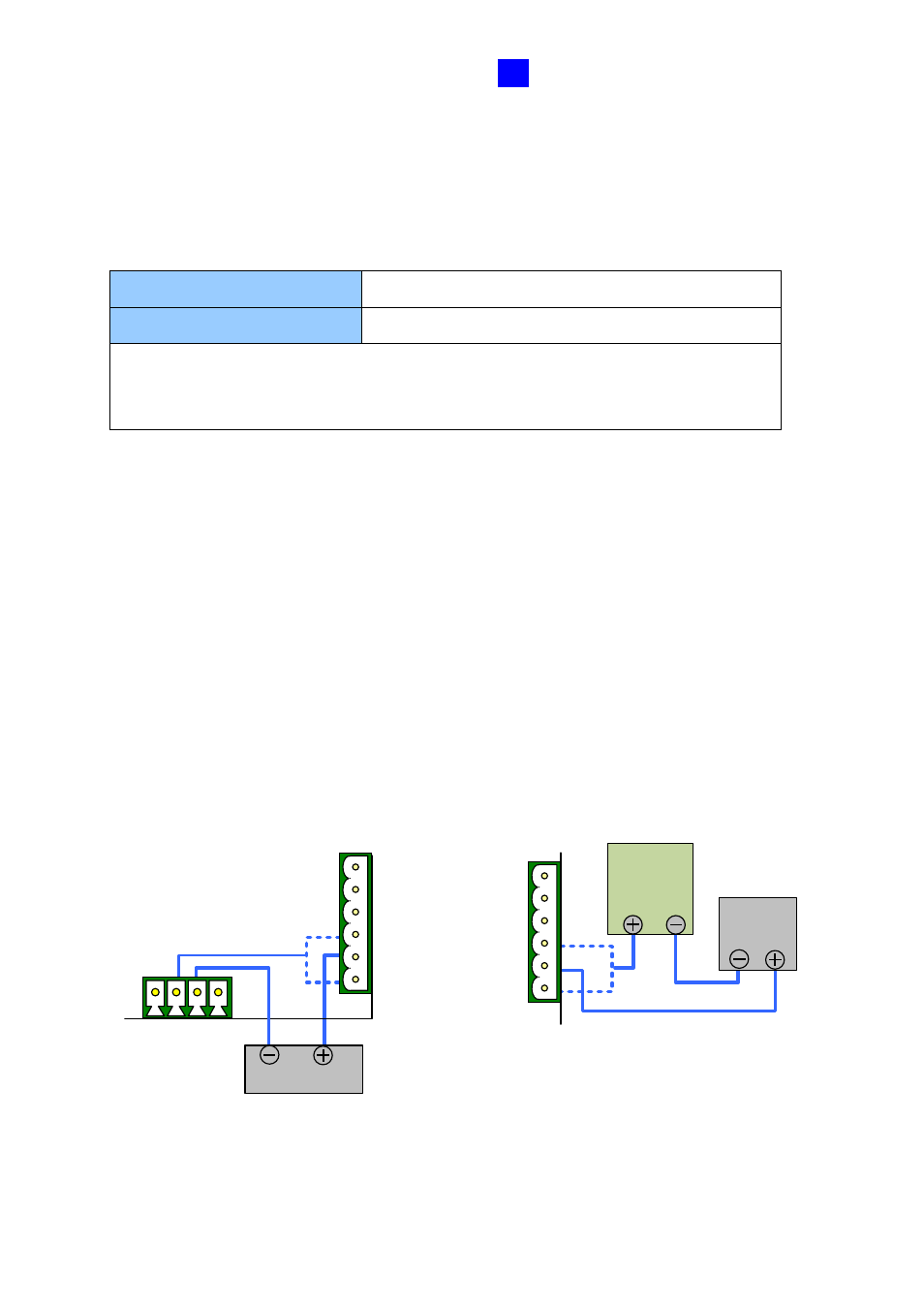
To connect an output device:
Connect the (+) point on the output device to COM on GV-AS210 / 2110 / 2120, connect the
two (-) points of the output device and the power supply together, and connect the (+) point
on the power supply to the NO or NC of GV-AS210 / 2110 / 2120 based on the state of the
output device.
There are two ways to supply power to the output device:
⚫
Use the power outputs on the GV-AS Controller:
The output device must be a 12V
device. The total power consumption of the output devices and readers connected to
the controller must be under 3A when using the power adapter. If you are using a PoE
adapter for GV-AS2120, the total power consumption must be under 25.5 W.
⚫
Connect an external power supply:
Connect an external power supply if the total
power consumption is exceeded or if the output device requires higher current.
NC2
COM2
NO2
NC1
COM1
NO1
Output Device
External
Power
Supply
Output
Device
NC2
COM2
NO2
NC1
COM1
NO1
12
V
12
V
G
N
D
G
N
D
Figure 4-6